Opis
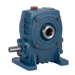
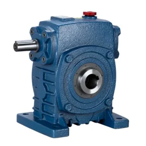
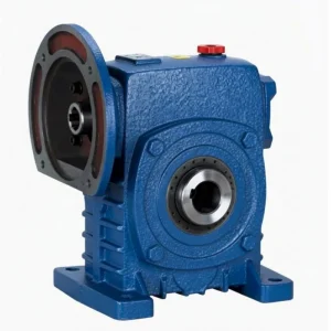
WPWDKA Universal Speed Cast Iron Worm Reducer — Product Overview
Zero coupling hardware at both ends, in-situ maintenance access, in any of 5 WPW mounting orientations — the maximum-specification A-type universal reducer.
Obudowa WPW P mieści wszystkie pięć standardowych konfiguracji kierunku wału w jednym odlewie, eliminując potrzebę stosowania obudów dostosowanych do konkretnego kierunku. Moc wejściowa od 0,06 kW (rozmiar 40) do 98 kW (rozmiar 250), momenty wyjściowe od 2,2 Nm do 4440 Nm w 11 standardowych rozmiarach.
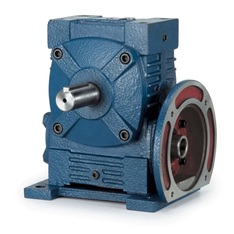
WPWDKA Universal Speed Worm Reducer Specifications
| Parametr | Specyfikacja |
|---|---|
| Szereg | Uniwersalna prędkość WPW |
| Mieszkania | Zero coupling hardware at both ends, in-situ maintenance acc |
| Wejście | IEC motor flange, A-type (below) |
| Wyjście | Hollow bore (K-type) |
| Stosunek | 1/5–1/60 |
| Zakres rozmiarów | 40–250 mm |
| Montowanie | Mocowanie na stopę, korpus uniwersalny WPW, wszystkie orientacje |
| Materiał obudowy | Żeliwo szare FC20+ (GG20) |
| Koło ślimakowe | Brąz cynowy ZCuSn10Pb1 |
| Wał ślimakowy | 20CrMnTi, powierzchnia 55–60 HRC |
| Smarowanie | N150–N220 (−30°C–40°C); N220–N320 (40°C–65°C) |
| Maksymalna temperatura oleju | 95°C w trybie ciągłym |
| Zakres wagowy | 6,5/7–430/481 kg |
| Kluczowa cecha | Four Features: Universal Body + D-Split + IEC A-Flange + K Hollow Bore |
Dane dotyczące rozmiaru i wydajności
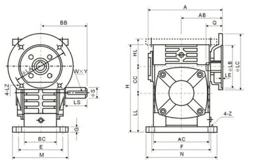
| Rozmiar (mm) | Stosunek | Moc wejściowa (kW) | Moment obrotowy wyjściowy (Nm) | A (mm) | AA (mm) | AB (mm) | BB (mm) | Waga (kg) |
|---|---|---|---|---|---|---|---|---|
| 40 | 1/5–1/60 | 0,06–0,78 | 2,2–26,5 | 121/133 | 53 | 40 | 49/62 | 6.5/7 |
| 50 | 1/5–1/60 | 0,10–1,33 | 4,5–54,0 | 133/148 | 57 | 44 | 55/70 | 9/10 |
| 63 | 1/5–1/60 | 0,19–2,25 | 8,5–104 | 155/171 | 67 | 51 | 65/82 | 14/16 |
| 75 | 1/5–1/60 | 0,32–3,75 | 14,5–175 | 175/191 | 75 | 57 | 73/91 | 20/23 |
| 90 | 1/5–1/60 | 0,62–6,98 | 28–316 | 205/224 | 89 | 67 | 87/107 | 33/38 |
| 110 | 1/5–1/60 | 1,18–11,9 | 53–540 | 238/260 | 103 | 78 | 101/123 | 54/62 |
| 130 | 1/5–1/60 | 2,02–19,7 | 91–891 | 266/290 | 115 | 87 | 112/136 | 78/89 |
| 150 | 1/5–1/60 | 3,07–28,8 | 139–1304 | 302/329 | 131 | 100 | 128/155 | 113/128 |
| 175 | 1/5–1/60 | 5,13–45,9 | 232–2074 | 348/377 | 151 | 115 | 147/177 | 170/191 |
| 200 | 1/5–1/60 | 8,02–66,2 | 363–2993 | 392/424 | 170 | 130 | 165/199 | 250/265 |
| 250 | 1/5–1/60 | 13,0–98,0 | 590–4440 | 452/481 | 197 | 150 | 195/232 | 380/420 |
WPWDKA Worm Reducer — Core Features
■ Four Features: Universal Body + D-Split + IEC A-Flange + K Hollow Bore
Zero coupling hardware at both ends, in-situ maintenance access, in any of 5 WPW mounting orientations — the maximum-specification A-type universal reducer.
■ IEC A-Type Flange — Direct Motor Mount from Below
A-type IEC flange eliminates the motor adaptor. Motor bolts on in four bolts from below in any WPW orientation.
■ K Hollow Bore — Coupling-Free Shaft at Any Orientation
Driven shaft inserts directly through the K-bore in any WPW orientation — no coupling hardware at the output.
■ D-Split Cover — In-Situ Access in Any Orientation
Cover removes for worm wheel inspection in any WPW mounting orientation with motor and shaft connected.
■ One Product — Complete Motorised Hollow Bore A-Type Drive
Eliminates all direction-specific motorised hollow bore A-type reducer variants — one WPWDKA covers all requirements.
■ Output Torque to 4,440 Nm — Full Capacity
Four features do not reduce torque ratings. Size 250 delivers 4,440 Nm.
WPWDKA Worm Reducer — Industry Applications

⚒ Maximum-Integration A-Type Universal Drive
OEM builders standardise all motorised hollow bore A-type drives on WPWDKA — zero coupling hardware, in-situ access, universal body.
⚊ Multi-Position Motorised Shaft-Mount Drives
Equipment with motor-direct hollow bore shaft drives in multiple orientations standardises on WPWDKA.
☷ Agricultural Motorised Hollow Shaft Platform
Agricultural machinery with motor-direct shaft drives in varied positions uses WPWDKA to standardise the complete drive system.
⚙ Process Plant Universal Motor-Direct Shaft Drives
Process plants with motor-direct hollow bore drives in multiple orientations use WPWDKA for simplified procurement and maintenance.
Ever Power Manufacturing Quality — WPWDKA Worm Reducer
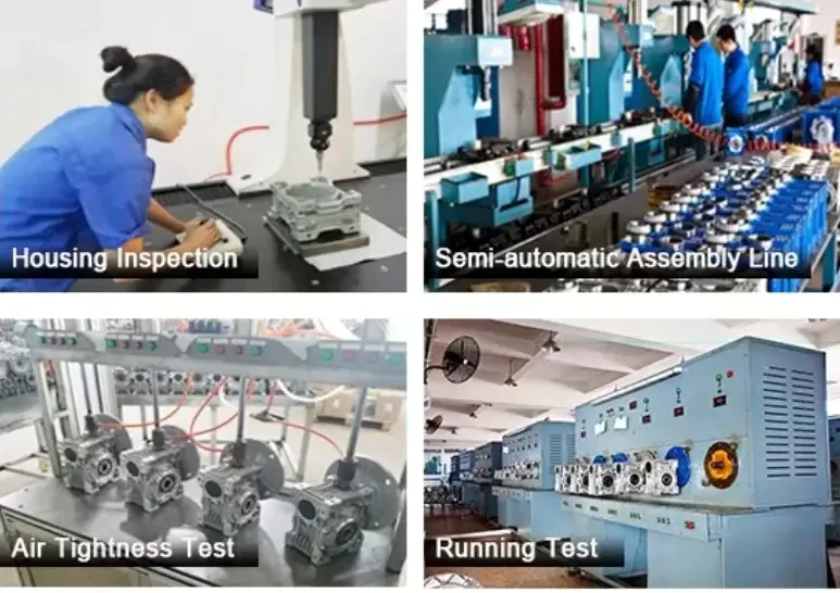
■ Produkcja z certyfikatem ISO 9001:2000
Każda jednostka WPW jest produkowana zgodnie z systemem zarządzania jakością ISO 9001:2000. Kontrola surowców, kontrole w trakcie produkcji oraz testy końcowe są dokumentowane i możliwe do prześledzenia.
■ Oznakowanie CE — Dyrektywa maszynowa UE 2006/42/WE
Pełna zgodność z normami CE w przypadku eksportu do rynków UE, Wielkiej Brytanii, Australii i Nowej Zelandii.
■ Testowanie przed wysyłką: hałas, nieszczelność, moment obrotowy
Hałas poniżej 68 dB(A) przy obciążeniu znamionowym, 30-minutowy test szczelności i moment obrotowy wyjściowy w granicach ±5% od wartości znamionowej. Urządzenia niezgodne z wymaganiami są przerabiane przed wysyłką.
■ Certyfikacja materiałów FC20+
Odlewy obudów potwierdzone certyfikatami hutniczymi: wytrzymałość na rozciąganie minimum 220 MPa, twardość 160–200 HB.
WPWDKA Universal Worm Reducer — Customer Reviews
“WPWDKA on our multi-orientation machine drives. IEC A-type motor, K-bore output, D-split — zero coupling hardware everywhere. One product, all positions.”
“Used WPWDKA on agricultural equipment. IEC motor direct, hollow bore shaft, universal body. Best-integrated drive we’ve used on this machine type.”
“WPWDKA on our process plant motor-direct shaft drives. Universal body, IEC flange, K-bore, D-split. Standardised all positions on one product.”
“Good four-feature A-type universal unit. WPWDKA-90 in multiple positions. All working. Would like IEC frame size guide for A-type orientation.”
Frequently Asked Questions — WPWDKA Universal Speed Worm Reducer
Get Your WPWDKA Quote Today
Poinformuj Ever Power o swoich wymaganiach dotyczących zastosowania – momencie obrotowym, przełożeniu, montażu i wymiarach wału. Odpowiedź inżynierska w ciągu 24 godzin. Dostępne są specyfikacje OEM, ceny hurtowe i wysyłka na cały świat.