Beschreibung
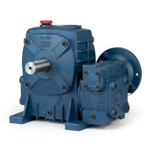
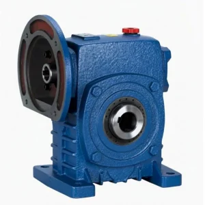
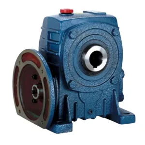
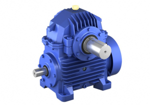
WPWED Double Speed Cast Iron Worm Reducer — Product Overview
Where the WPWE covers all shaft directions at extreme ratios, the WPWED adds the two features that motorised OEM applications most frequently require: direct IEC motor mounting without adaptor plate, and D-split cover for in-situ worm wheel inspection. The result is a universal motorised extreme-ratio platform — one product covering multiple machine shaft directions, direct motor connection at any orientation, and planned maintenance access without unit removal.
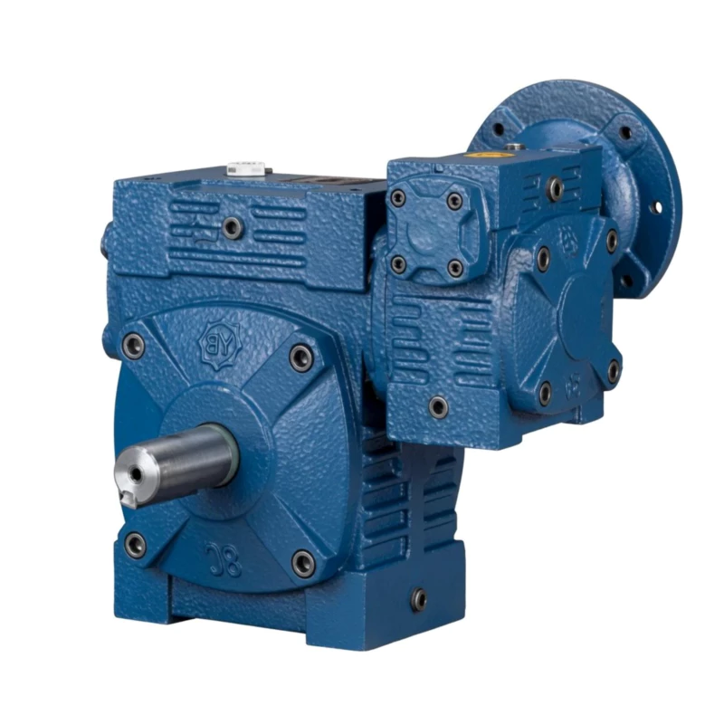
WPWED Double Speed Worm Reducer Specifications
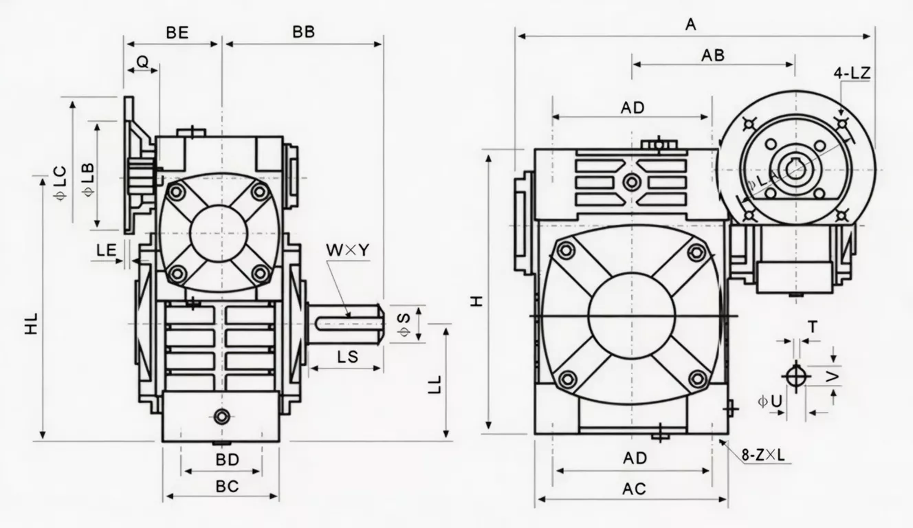
| Parameter | Spezifikation |
|---|---|
| Serie | Double Speed WPWE+D |
| Gehäuse | D-förmig geteiltes Gusseisen, zweistufig, WPW-Universalgehäuse |
| Eingang | IEC motor flange — D-type, multiple shaft directions |
| Ausgabe | Solid shaft — multiple WPW directions |
| Verhältnisbereich | 1/200–1/900+ |
| Größenkombinationen | 40–70 bis 155–250 mm |
| Montage | Foot-mount, D-split, IEC flange, WPW universal body |
| Gehäusematerial | FC20+ Grauguss, Zweikammer |
| Schneckenräder | Gepaartes Zinnbronze-ZCuSn10Pb1, beide Stufen |
| Schneckenwellen | 20CrMnTi einsatzgehärtet 55–60 HRC, beide Stufen |
| Schmierung | N220–N320 (−30 °C–40 °C); N320–N460 (40 °C–65 °C), beide Kammern |
| Maximale Öltemperatur | 95 °C kontinuierlich |
| Gewichtsbereich | 19–450 kg |
| Hauptmerkmal | WPW universal body + D-IEC flange + D-split + double-stage — universal motorised extreme ratio platform |
Größenkombination & Leistungsdaten
| Größenkombination | Verhältnis | Eingangsleistung (kW) | Ausgangsdrehmoment (Nm) | A (mm) | AA (mm) | AB (mm) | BB (mm) | Gewicht (kg) |
|---|---|---|---|---|---|---|---|---|
| 40–70 | 1/200 | 0.12 | 63–177 | 314 | 153 | 131 | 75 | 19 |
| 50–80 | 1/300 | 0.18 | 97–252 | 314 | 144 | 142 | 83 | 27 |
| 60–100 | 1/400 | 0.37 | 195–561 | 387 | 175 | 169 | 91 | 45 |
| 70–120 | 1/500 | 0.75 | 384–1166 | 425/445 | 193 | 175 | 109/111 | 75 |
| 80–135 | 1/600 | 1.5 | 616–1811 | 499 | 226 | 210 | 125 | 103 |
| 100–155 | 1/800 | 1.5 | 854–2100 | 570 | 269 | 252 | 148 | 147 |
| 120–175 | 1/900 | 3.0 | 1.798–4.463 | 631 | 287 | 255 | 181 | 204 |
| 135–200 | 1/900+ | 4.0 | 2.188–5.830 | 630/680 | 318 | — | 202 | 298 |
| 155–250 | 1/900+ | 5.5 | 2.841–9.066 | 815 | 380 | 385 | 247 | 470 |
WPWED Double Speed Worm Reducer — Core Features
■ WPW Universal Body + IEC Flange + D-Split + Double Stage
The WPWED builds on the WPWE universal body by adding IEC direct motor mounting (no adaptor) and D-type split housing (in-situ maintenance cover). All WPW shaft direction configurations remain available — extreme ratio, universal orientation, direct motor, in-situ access.
■ D-Split Cover — In-Situ Access at Any WPW Shaft Direction
The D-split housing cover can be removed for worm wheel inspection regardless of which WPW shaft direction configuration is in use — universal maintenance access across all orientations.
■ IEC Motor Flange — No Adaptor in Any Shaft Direction
The IEC 72-1 flange is integrated at the input position regardless of WPW shaft direction — direct motor mount without adaptor plate in all WPWED configurations.
■ Output Torque to 9,066 Nm — Universal Body Full Capacity
WPWED worm gear internals are identical to WPEDA. Universal body does not reduce torque capacity — size 155–250 delivers up to 9,066 Nm.
■ Single Universal Model — Multiple Machine Drive Orientations
WPWED covers all shaft direction requirements of a multi-orientation OEM machine in a single universal model — reducing BOM complexity, spare parts inventory, and maintenance training requirements.
■ Dual Independent Oil Chambers — Direction-Adjusted Volumes
Both stage chambers are independently sealed. Oil volumes are specified per WPW shaft direction in the WPWED lubrication table.
WPWED Worm Reducer — Industry Applications

⚒ Universal OEM Machine Motorised Drive Platform
OEM machine builders use WPWED as the single extreme-ratio motorised drive platform for all shaft direction requirements — IEC motor direct, in-situ maintenance access, and 1/200–1/900+ ratio across every machine drive position.
⚊ Multi-Orientation Processing Line Drives
Packaging and food processing lines with drives in multiple orientations standardise on WPWED for all extreme-ratio motor-direct drive positions — one product, all orientations, planned maintenance access in position.
⚙ Infrastructure & Utility Slow Drives
Dam gates, sluice controls, and utility infrastructure slow drives in multiple shaft direction configurations use WPWED for its combination of direct motor mounting, extreme ratio, and in-situ maintenance capability.
☷ Agricultural Machinery Multi-Axis Drives
Complex agricultural machinery with motor-direct slow drives in multiple axis directions uses WPWED universal body to standardise the complete slow-speed drive system on one product family.
Ever Power Manufacturing Quality — WPWED Worm Reducer
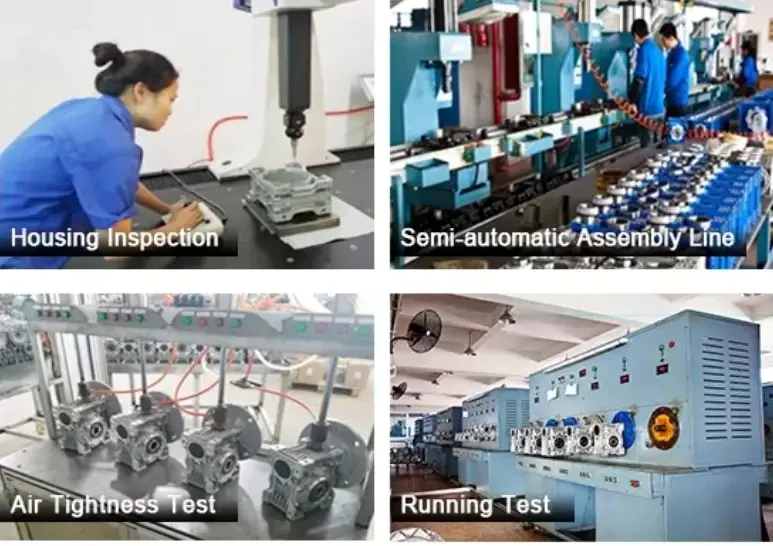
■ ISO 9001:2000 — Zweistufige Montage zertifiziert
Beide Schneckenstufen werden gemäß ISO 9001:2000 gefertigt und geprüft. Die Ausrichtung zwischen den Stufen und die Übersetzungsgenauigkeit werden vor der Endmontage jeder Einheit überprüft.
■ CE-Kennzeichnung – EU-Maschinenrichtlinie 2006/42/EG
Volle CE-Konformität für den Export in die EU, nach Großbritannien, Australien und Neuseeland ohne erneute Zertifizierung.
■ Prüfung vor dem Versand: Geräusche, Leckage, Drehmoment
Geräuschpegel unter 68 dB(A) bei Nennlast, 30-minütige Druckbeaufschlagung beider Getriebekammern und Abtriebsdrehmoment innerhalb von ±51 TP3T des Nenndrehmoments. Nicht konforme Einheiten werden vor dem Versand nachbearbeitet.
■ FC20+ Materialzertifizierung
Beide Gehäuse verfügen über Werkszeugnisse gemäß FC20: Mindestzugfestigkeit 220 MPa, Härte 160–200 HB. Ultraschallprüfung bei Größenkombinationen ab 135–200.
WPWED Double Speed Worm Reducer — Customer Reviews
“WPWED as our universal motorised drive platform across our packaging machine. IEC motor direct, D-split for maintenance, WPW body covers all our shaft direction requirements. One spare part for the entire line.”
“Used WPWED on infrastructure slow drives. Direct IEC motor at 1/800 ratio, 2,100 Nm output, D-split inspection in position, universal body for different installation configurations. Excellent engineering.”
“WPWED on our food processing line motor-direct drives. Universal body, IEC flange, split cover — covers every drive orientation in the plant with one product model. Simplified our maintenance programme.”
“Good universal motorised double-stage unit. WPWED-80–135 across our OEM machine. All features working as specified. Would appreciate a comprehensive shaft direction configuration guide from Ever Power.”
Frequently Asked Questions — WPWED Double Speed Worm Reducer
Get Your WPWED Quote Today
Teilen Sie Ever Power Ihre Anwendungsanforderungen mit – Drehmoment, Übersetzungsverhältnis, Montageart und Wellenabmessungen. Sie erhalten innerhalb von 24 Stunden eine Antwort von unserer Entwicklungsabteilung. OEM-Spezifikationen, Mengenrabatte und weltweiter Versand sind verfügbar.