Description
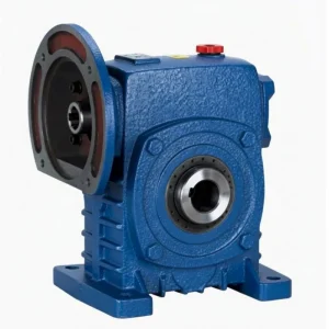
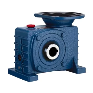
WPES Double Speed Cast Iron Worm Reducer — Product Overview
Single-stage worm reducers achieve ratios up to 1/60. When applications demand 1/200, 1/500, or 1/900 — solar trackers, valve actuators, slow-speed conveyors, and positioning drives — a second worm stage is the engineering answer. The WPES places two matched worm stages in tandem in a single cast iron housing, delivering ratios from 1/200 to over 1/900 in one compact, foot-mount unit with no intermediate shafting, no external coupling between stages, and no additional mounting frame.
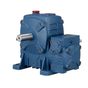
Combines two worm stages with S-type top-entry input, enabling the motor to mount overhead while achieving ratios that n… The dual-stage architecture uses matched tin-bronze worm wheels and 20CrMnTi worm shafts at both stages, providing consistent mesh quality and noise performance across the full ultra-high ratio range.
WPES Double Speed Worm Reducer Specifications
| Paramètre | Spécification |
|---|---|
| Series | Double Speed WPE+S |
| Housing | Solid integral cast iron, dual-stage |
| Input | Solid shaft — above (S-type) |
| Output | Solid shaft, horizontal |
| Ratio Range | 1/200–1/900+ |
| Size Combinations | 40–70 to 155–250 mm |
| Montage | Foot-mount, S-type top-entry input |
| Matériau du boîtier | FC20+ grey cast iron, dual-chamber |
| Worm Wheels | Matched pair tin-bronze ZCuSn10Pb1, both stages |
| Worm Shafts | 20CrMnTi case-hardened 55–60 HRC, both stages |
| Lubrication | N220–N320 (−30°C–40°C); N320–N460 (40°C–65°C), both chambers |
| Max Oil Temp | 95°C continuous |
| Weight Range | 20–462 kg |
| Key Feature | Double-stage + S overhead input — ultra-high ratio with vertical motor geometry |
Size Combination & Performance Data
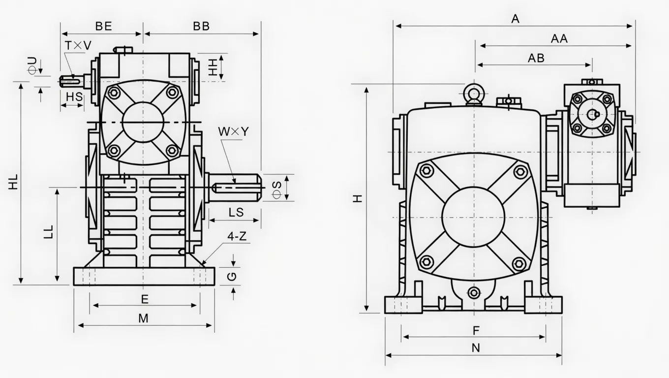
| Size Combo | Ratio | Input (kW) | Output Torque (Nm) | A (mm) | AA (mm) | AB (mm) | BB (mm) | Weight (kg) |
|---|---|---|---|---|---|---|---|---|
| 40–70 | 1/200 | 0.48 | 250 | 286 | 195 | 153 | 131 | 20 |
| 50–80 | 1/300 | 0.65 | 350 | 297 | 197 | 144 | 142 | 27 |
| 60–100 | 1/400 | 0.95 | 500 | 363 | 231 | 175 | 169 | 44 |
| 70–120 | 1/500 | 1.64 | 840 | 408 | 256 | 193 | 190 | 73 |
| 80–135 | 1/600 | 2.5 | 1,400 | 471 | 298 | 226 | 210 | 101 |
| 100–155 | 1/800 | 3.69 | 2,100 | 555 | 354 | 269 | 252 | 144 |
| 120–175 | 1/900 | 5.09 | 3,050 | 568 | 379 | 287 | 255 | 201 |
| 135–200 | 1/900+ | 7.22 | 3,950 | 662 | 425 | 318 | 319 | 293 |
| 155–250 | 1/900+ | 11.71 | 6,050 | 795 | 510 | 380 | 385 | 462 |
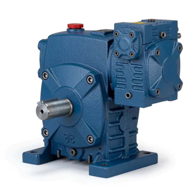
WPES Double Speed Worm Reducer — Core Features
■ S-Type Top-Entry + Double Stage — Overhead Motor at 1/200–1/900+
Combines two worm stages with S-type top-entry input, enabling the motor to mount overhead while achieving ratios that no single-stage reducer can reach. Reduces lateral machine footprint at ultra-high ratio.
■ Same Torque Ratings as WPEA — S Input Does Not Reduce Capacity
S-type top-entry designation changes input shaft direction only. WPES worm gear internals and torque ratings are identical to the WPEA — up to 6,050 Nm from size combination 155–250.
■ Matched Dual-Stage Worm Wheels — Both Stages
Both reduction stages use precision-matched ZCuSn10Pb1 tin-bronze worm wheel pairs for consistent inter-stage ratio accuracy across the full 1/200–1/900+ range.
■ Overhead Motor Reduces Lateral Footprint
S-type input positions the motor vertically above the dual-stage reducer. In confined-width installations where lateral motor projection would exceed available space, WPES resolves the constraint without sacrificing ratio capability.
■ Bilateral Input Option Maintained
The S-type top-entry input shaft extends on both sides, accepting coupling connections from either direction — the same flexibility as the standard WPS single-stage unit.
■ FC20+ Dual-Chamber Cast Iron Housing
Single-cast dual-chamber housing from FC20+ grey cast iron maintains inter-stage alignment across the operating temperature range. No bolted joint between stages — worm shaft centreline geometry is set at manufacture.
WPES Worm Reducer — Industry Applications

☀ Overhead-Motor Solar Tracker Drives
WPES combines ultra-high ratio reduction with overhead motor geometry — reducing the lateral projection of the drive assembly on solar tracker frames where horizontal space between panels is constrained.
⚒ Valve Actuators in Tight Lateral Spaces
In pipe galleries and valve manifolds where lateral clearance beside the actuator drive is limited, WPES overhead motor positioning achieves the required 1/200–1/900+ ratio within the available installation envelope.
⚙ Slow-Speed Drives in Narrow Machine Frames
Machinery with constrained lateral width — narrow conveyors, slim elevator frames, compact processing lines — uses WPES to achieve ultra-high ratio reduction while keeping the motor above the frame rather than beside it.
⚊ Overhead-Driven Positioning Systems
Where the mechanical design requires the motor to be above the driven equipment and the output speed must be below 5 rpm, WPES is the standard double-stage solution.
Ever Power Manufacturing Quality — WPE Double Speed Worm Reducer
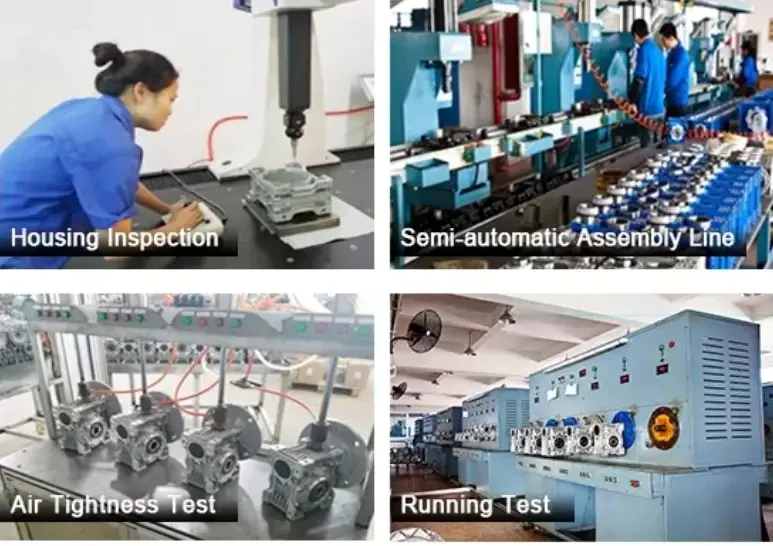
■ ISO 9001:2000 Certified — Dual-Stage Assembly
Every WPE double speed unit undergoes ISO 9001:2000 quality management at both worm stage assembly levels. Inter-stage alignment and combined ratio accuracy are verified before final assembly.
■ CE Marking — EU Machinery Directive 2006/42/EC
Full CE compliance for mechanical power transmission equipment supports export to EU, UK, Australian, and New Zealand markets without re-certification.
■ Pre-Shipment Testing: Noise, Leak, Torque
Noise below 68 dB(A) at rated load, 30-minute pressurisation leak test on both gear chambers, and output torque within ±5% of rated. Non-conforming units reworked before shipment.
■ FC20+ Material Certification — Both Housings
Both the primary and secondary worm housings are verified by FC20 mill certificates: minimum 220 MPa tensile strength, 160–200 HB hardness. Ultrasonic defect testing on size combinations 135–200 and above.
WPES Double Speed Worm Reducer — Customer Reviews
“WPES on our solar panel tracker drives where horizontal clearance between panel arrays is limited. Overhead motor plus 1/600 ratio gives us the tracking speed we need in a narrower drive envelope than the WPEA configuration.”
“Used WPES on our narrow-frame conveyor drives. Motor overhead keeps the drive within the frame width. 1/500 ratio gives us correct belt speed from a standard 4-pole motor. Good solution.”
“WPES on valve actuator drives in our pipe gallery. Limited lateral clearance made WPES the only workable option. Overhead motor, 1/800 ratio, correct torque output for the valve size. Works well.”
“Good S-type double-stage unit for overhead motor applications. WPES-80–135 on our positioning drives. Overhead motor reduces machine width. Would appreciate a combined S+K variant for shaft-mount applications.”
Frequently Asked Questions — WPES Double Speed Worm Reducer
Get Your WPES Quote Today
Tell Ever Power your application requirements — torque, ratio, mounting, and shaft dimensions. Engineering response within 24 hours. OEM specifications, bulk pricing, and global shipping available.