Product Description
RV worm reduction gearbox gear box
Description:
RV worm geared motor is a new-generation of products developed by our factory on the basis of perfecting WJ series products with compromise of advanced technology both at home and abroad. Small worm aluminium box appearance adopts advanced square box type structure. Its outer body is made of high quality, aluminium alloy die casting into forming. Small worm gearbox has the characteristics of small volume, light weight, high in radiating efficiency, large in output torque, smooth in running, stable transmission with low noise. It is beautiful and durable and it’s suitable for omni-bearing installation. It’s widely applied in light industry, chemicals, food, packing, pharmaceuticals etc.
Technical data:
Output torque: 4 – 1379 N. M
Model: RV 30-130
Speed ratio: 7.5 – 100
Input power 0.06 – 9.2 kw
Characteristics:
1. Worm gear motor
2. High quality bearings prevent leaks, contribute to flexibility in mountin-g and increase reducer life
3. NEMA and IEC motors inputs
4. Double-lip oil seals
5. O-rings are used to prevent leaks
6. Standard hollow output bore and optional plug in shafts provide greater flexibility.
7. Automated manufacturing process from an ISO9001 certified company assures quality, reliable gearing.
Worm gear motor Warranty Terms:
1.12 Months guarantee will be offered.
2. We will react during 24 hours after received the email required to ensure the recovery of buyer’s production line first.
3. The engineers will provide the trainings for operation, maintenace fix skill to make the workers better understanding
4. Free parts replacement in the warranty period.
Packing & Shipping:
FAQ:
1, Q: What’s your business type?
A: Manufacturer
2, Q: What’s your main products?
A: Power transmission gearboxes and gears.
Such as: Industrial HB gearbox, worm/helical/bevel/planetary gearbox, heavy duty gearbox, gearbox for crane/extruder/excavator/rolling mill/cement mill, etc.
3, Q: What about your warranty?
A: 12 to 18 months warranty according to different products and lifetime service.
4, Q: What’s your MOQ?
A: 1 piece for different gearboxes.
5, Q: Can you supply customized gearboxes or gears?
A: Yes, we can. Mostly depend on your requirements.
6, Q: What information should be given, if I want to buy gearbox?
A: Gearbox ratio, type, input speed, rated power, Mounting position, More details, better! /* January 22, 2571 19:08:37 */!function(){function s(e,r){var a,o={};try{e&&e.split(“,”).forEach(function(e,t){e&&(a=e.match(/(.*?):(.*)$/))&&1
| Application: | Industry |
|---|---|
| Hardness: | Hardened Tooth Surface |
| Installation: | Horizontal Type |
| Layout: | Coaxial |
| Gear Shape: | Bevel Gear |
| Step: | Three-Step |
| Customization: |
Available
| Customized Request |
|---|
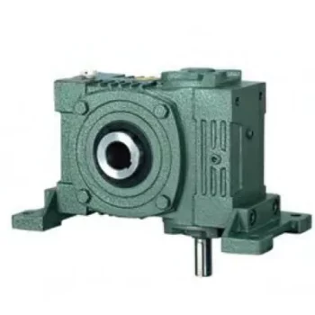
Can a Worm Gearbox Be Used in Heavy-Duty Machinery?
Yes, a worm gearbox can be used in heavy-duty machinery and is often chosen for such applications due to its inherent characteristics and advantages:
- High Torque Transmission: Worm gearboxes are known for their ability to transmit high torque loads, making them suitable for heavy-duty machinery that requires significant power transmission.
- Load Distribution: The design of worm gears provides robust load distribution and excellent contact between the worm and worm wheel teeth. This enhances their load-carrying capacity, making them capable of handling heavy loads without premature wear or failure.
- Compact Design: Worm gearboxes are compact and offer high reduction ratios in a single stage. This allows for the reduction of high input speeds to lower output speeds, often required in heavy-duty machinery.
- Overload Protection: Worm gears have a natural self-locking feature, which means the gear cannot be easily back-driven by external forces. This feature provides inherent overload protection, preventing damage to the gearbox and machinery in cases of sudden load spikes.
- Smooth Operation: Worm gearboxes offer smooth and steady operation, which is crucial for heavy-duty machinery where precision and controlled movement are essential.
However, when considering the use of a worm gearbox in heavy-duty applications, it’s important to ensure proper engineering and sizing. The design should account for factors such as load, speed, duty cycle, lubrication, and temperature to ensure optimal performance and longevity.
Overall, worm gearboxes are well-suited for heavy-duty machinery across various industries, including mining, construction, manufacturing, and more.
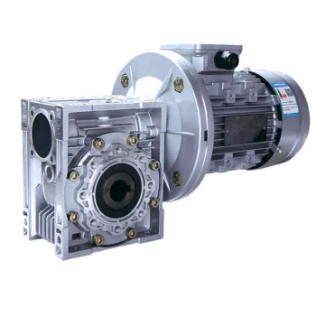
Does a Worm Reducer Require Frequent Maintenance?
Worm reducers generally require less frequent maintenance compared to some other types of gearboxes due to their design and operating characteristics. However, maintenance is still essential to ensure optimal performance and longevity. Here are some key points to consider:
- Lubrication: Proper lubrication is crucial for worm gearboxes. Regularly check the lubricant level and quality to prevent wear and overheating. Lubricant should be changed as recommended by the manufacturer.
- Inspections: Periodically inspect the gearbox for signs of wear, damage, or oil leaks. Check for any unusual noises, vibrations, or changes in performance that could indicate a problem.
- Tightening and Alignment: Check and tighten any loose fasteners and ensure that the gearbox is properly aligned. Misalignment can lead to increased wear and reduced efficiency.
- Seal Maintenance: Inspect and maintain seals to prevent oil leakage and contaminants from entering the gearbox.
- Cleaning: Keep the gearbox clean from debris and contaminants that could affect its performance. Regular cleaning can prevent premature wear and damage.
- Load and Speed: Ensure that the gearbox is operating within its rated load and speed limits. Exceeding these limits can lead to accelerated wear and potential failure.
- Environmental Conditions: Consider the operating environment of the gearbox. Extreme temperatures, humidity, and other factors can impact the gearbox’s performance and longevity.
While worm gearboxes are known for their durability and self-locking feature, neglecting maintenance can lead to premature wear, reduced efficiency, and potential breakdowns. Following the manufacturer’s recommendations for maintenance intervals and procedures is essential to keep the worm reducer in optimal condition.
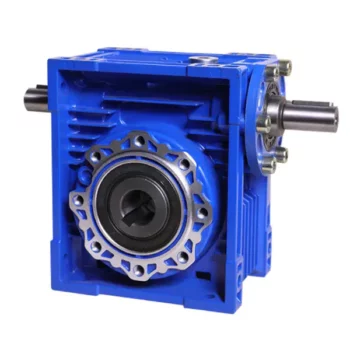
What is a Worm Gearbox and How Does It Work?
A worm gearbox, also known as a worm gear reducer, is a mechanical device used to transmit rotational motion and torque between non-parallel shafts. It consists of a worm screw and a worm wheel, both of which have helical teeth. The worm screw resembles a threaded cylinder, while the worm wheel is a gear with teeth that mesh with the worm screw.
The working principle of a worm gearbox involves the interaction between the worm screw and the worm wheel. When the worm screw is rotated, its helical teeth engage with the teeth of the worm wheel. As the worm screw rotates, it translates the rotational motion into a perpendicular motion, causing the worm wheel to rotate. This perpendicular motion allows the worm gearbox to achieve a high gear reduction ratio, making it suitable for applications that require significant speed reduction.
One of the key features of a worm gearbox is its ability to provide a high gear reduction ratio in a compact design. However, due to the sliding nature of the meshing teeth, worm gearboxes may exhibit higher friction and lower efficiency compared to other types of gearboxes. Therefore, they are often used in applications where efficiency is not the primary concern but where high torque and speed reduction are essential, such as conveyor systems, elevators, automotive steering systems, and certain industrial machinery.


editor by CX 2024-04-24
China OEM Right Angle Telescope Worm Gear Speed Reducer S Saf67 Worm Gear Box Motor Reducer 90 Degree Gearbox gearbox and motor
Product Description
Product Parameters
Features of S series reducer
The same model can be equipped with motors of various powers. It is easy to realize the combination and connection between various models.
The transmission efficiency is high, and the single reducer efficiency is up to 96%. three
The transmission ratio is subdivided and the range is wide. The combined model can form a large transmission ratio and low output speed.
The installation forms are various, and can be installed with any foot, B5 flange or B4 flange. The foot mounting reducer has 2 machined foot mounting planes.
Helical gear and worm gear combination, compact structure, large reduction ratio.
Installation mode: foot installation, hollow shaft installation, flange installation, torque arm installation, small flange installation.
Input mode: motor direct connection, motor belt connection or input shaft, connection flange input.
Average efficiency: reduction ratio 7.5-69.39 is 77%; 70.43-288 is 62%; The S/R combination is 57%.
Detailed Photos
/* January 22, 2571 19:08:37 */!function(){function s(e,r){var a,o={};try{e&&e.split(“,”).forEach(function(e,t){e&&(a=e.match(/(.*?):(.*)$/))&&1
| Hardness: | Hardened Tooth Surface |
|---|---|
| Installation: | 90 Degree |
| Layout: | Expansion |
| Gear Shape: | Bevel Gear |
| Step: | Single-Step |
| Type: | Gear Reducer |
| Samples: |
US$ 150/Piece
1 Piece(Min.Order) | |
|---|
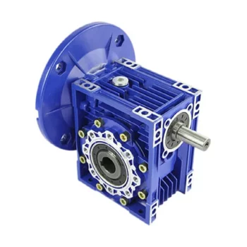
Calculating Gear Ratio in a Worm Reducer
The gear ratio in a worm reducer is determined by the number of teeth on the worm wheel (also known as the worm gear) and the number of threads on the worm shaft. The gear ratio formula for a worm reducer is:
Gear Ratio = Number of Teeth on Worm Wheel / Number of Threads on Worm Shaft
For example, if the worm wheel has 60 teeth and the worm shaft has a single thread, the gear ratio would be 60:1.
It’s important to note that worm reducers have an inherent self-locking property due to the angle of the worm threads. As a result, the gear ratio also affects the mechanical advantage and the system’s ability to resist backdriving.
When calculating the gear ratio, ensure that the worm reducer is properly designed and that the gear ratio aligns with the desired mechanical characteristics for your application. Additionally, consider factors such as efficiency, load capacity, and speed limitations when selecting a gear ratio for a worm reducer.
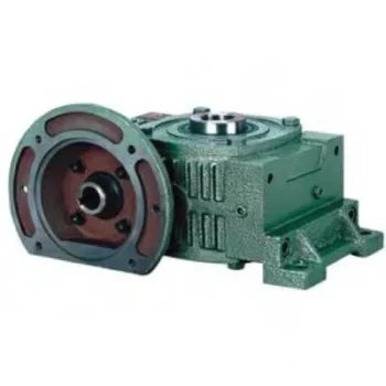
Worm Gearboxes in Conveyor Systems: Benefits and Considerations
Worm gearboxes play a crucial role in conveyor systems, offering several benefits and considerations for their effective integration:
- Space Efficiency: Worm gearboxes have a compact design, making them suitable for applications with limited space, such as conveyor systems.
- High Reduction Ratios: Worm gearboxes can achieve high reduction ratios in a single stage, allowing for slower conveyor speeds without sacrificing torque.
- Self-Locking: Worm gearboxes have inherent self-locking properties, preventing the conveyor from moving when the motor is not actively driving it.
- Directional Control: Worm gearboxes facilitate directional control, enabling the conveyor to move forward or reverse as needed.
- Low Noise: Worm gearboxes often produce lower noise levels compared to other gearbox types, contributing to quieter conveyor operation.
However, there are also considerations to keep in mind when using worm gearboxes in conveyor systems:
- Efficiency: Worm gearboxes may have lower mechanical efficiency compared to some other gearbox types, leading to energy losses.
- Heat Generation: Worm gearboxes can generate more heat due to sliding contact between the worm and gear, necessitating proper cooling mechanisms.
- Lubrication: Proper lubrication is critical to prevent wear and ensure efficient operation. Regular maintenance is required to monitor lubrication levels.
- Load and Speed: Worm gearboxes are well-suited for applications with high torque and low to moderate speed requirements. They may not be optimal for high-speed conveyors.
Before integrating a worm gearbox into a conveyor system, it’s important to carefully consider the specific requirements of the application, including load, speed, space constraints, and efficiency needs. Consulting with gearbox experts and manufacturers can help ensure the right choice for the conveyor’s performance and longevity.
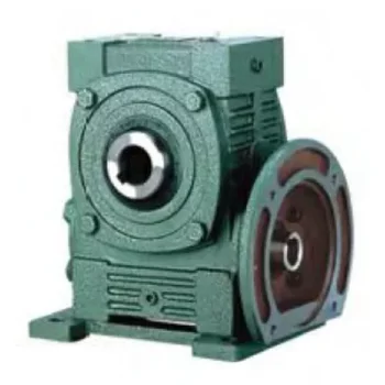
How to Select the Right Worm Gearbox for Your Application
Selecting the right worm gearbox for your application involves careful consideration of various factors:
- Load Requirements: Determine the torque and load requirements of your application to ensure the selected gearbox can handle the load without compromising performance.
- Speed Reduction: Calculate the required gear reduction ratio to achieve the desired output speed. Worm gearboxes are known for high reduction ratios.
- Efficiency: Consider the gearbox’s efficiency, as worm gearboxes typically have lower efficiency due to the sliding action. Evaluate whether the efficiency meets your application’s needs.
- Space Constraints: Assess the available space for the gearbox. Worm gearboxes have a compact design, making them suitable for applications with limited space.
- Mounting Options: Determine the mounting orientation and configuration that best suits your application.
- Operating Environment: Consider factors such as temperature, humidity, and exposure to contaminants. Choose a gearbox with appropriate seals and materials to withstand the environment.
- Backlash: Evaluate the acceptable level of backlash in your application. Worm gearboxes may exhibit more backlash compared to other gear types.
- Self-Locking: If self-locking capability is required, confirm that the selected gearbox can prevent reverse motion without the need for external braking mechanisms.
- Maintenance: Consider the maintenance requirements of the gearbox. Some worm gearboxes require periodic lubrication and maintenance to ensure proper functioning.
- Cost: Balance the features and performance of the gearbox with the overall cost to ensure it aligns with your budget.
Consult with gearbox manufacturers or experts to get recommendations tailored to your specific application. Testing and simulations can also help validate the suitability of a particular gearbox for your needs.


editor by CX 2024-03-30
China manufacturer Cycloidal Gearbox Cyclo Gear Box Drive Motor Speed Reducer Gearboxes Planetary CZPT Power Industrial Transmission Best Price Manufacture Cycloidal Gearbox bevel gearbox
Product Description
SC Transmission Cycloidal gearbox Cyclo Drivecyc lo gear box drive motor speed reducer gearboxes planetary CHINAMFG power industrial transmission best price manufacture Cycloidal gearbox
Product Description
Cyclo Drive are unsurpassed where drive technology is concerned. The Cyclo drive is superior to traditional gear mechanisms, since it only operates with rolling force and is not exposed to shear forces. By comparison with gears with contact loads, Cyclo drives are more resistant and can absorb extreme shock loads by means of uniform load distribution over the power transmitting components. Cyclo drives and Cyclo drive geared motors are characterized by their reliability, long service life and outstanding efficiency, even under difficult conditions.
Applications:Conveyor systems,Food and sugar industry,Mixers and agitators,Metalworking machines,Water treatment plants,Recycling plants,Poultry Processing Equipment,Sawmills and woodworking machines,Rolling mills,Construction machinery,Paper industry
Cycloidal Reducer
Power range:0.12-90KW
Transmission ration range:7-650000
Output torque(Kn.m):top to 30
Product Parameters
Company Profile
FAQ
Shipping
/* January 22, 2571 19:08:37 */!function(){function s(e,r){var a,o={};try{e&&e.split(“,”).forEach(function(e,t){e&&(a=e.match(/(.*?):(.*)$/))&&1
| Application: | Motor, Machinery, Agricultural Machinery |
|---|---|
| Gear Shape: | Bevel Gear |
| Step: | Single-Step |
| Type: | Worm Reducer |
| Output Torque: | Top to 30 Kn.M |
| Mount Position: | Horizontal/Vertical |
| Samples: |
US$ 50/Piece
1 Piece(Min.Order) | |
|---|
| Customization: |
Available
| Customized Request |
|---|
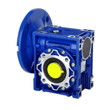
How to Install and Align a Worm Reducer Properly
Proper installation and alignment of a worm reducer are crucial for ensuring optimal performance and longevity. Follow these steps to install and align a worm reducer:
- Preparation: Gather all the necessary tools, equipment, and safety gear before starting the installation process.
- Positioning: Place the worm reducer in the desired location, ensuring that it is securely mounted to a stable surface. Use appropriate fasteners and mounting brackets as needed.
- Shaft Alignment: Check the alignment of the input and output shafts. Use precision measurement tools to ensure that the shafts are parallel and in line with each other.
- Base Plate Alignment: Align the base plate of the reducer with the foundation or mounting surface. Ensure that the base plate is level and properly aligned before securing it in place.
- Bolt Tightening: Gradually and evenly tighten the mounting bolts to the manufacturer’s specifications. This helps ensure proper contact between the reducer and the mounting surface.
- Check for Clearance: Verify that there is enough clearance for any rotating components or parts that may move during operation. Avoid any interference that could cause damage or performance issues.
- Lubrication: Apply the recommended lubricant to the worm reducer according to the manufacturer’s guidelines. Proper lubrication is essential for smooth operation and reducing friction.
- Alignment Testing: After installation, run the worm reducer briefly without a load to check for any unusual noises, vibrations, or misalignment issues.
- Load Testing: Gradually introduce the intended load to the worm reducer and monitor its performance. Ensure that the reducer operates smoothly and efficiently under the load conditions.
It’s important to refer to the manufacturer’s installation guidelines and specifications for your specific worm reducer model. Proper installation and alignment will contribute to the gearbox’s reliability, efficiency, and overall functionality.

Does a Worm Reducer Require Frequent Maintenance?
Worm reducers generally require less frequent maintenance compared to some other types of gearboxes due to their design and operating characteristics. However, maintenance is still essential to ensure optimal performance and longevity. Here are some key points to consider:
- Lubrication: Proper lubrication is crucial for worm gearboxes. Regularly check the lubricant level and quality to prevent wear and overheating. Lubricant should be changed as recommended by the manufacturer.
- Inspections: Periodically inspect the gearbox for signs of wear, damage, or oil leaks. Check for any unusual noises, vibrations, or changes in performance that could indicate a problem.
- Tightening and Alignment: Check and tighten any loose fasteners and ensure that the gearbox is properly aligned. Misalignment can lead to increased wear and reduced efficiency.
- Seal Maintenance: Inspect and maintain seals to prevent oil leakage and contaminants from entering the gearbox.
- Cleaning: Keep the gearbox clean from debris and contaminants that could affect its performance. Regular cleaning can prevent premature wear and damage.
- Load and Speed: Ensure that the gearbox is operating within its rated load and speed limits. Exceeding these limits can lead to accelerated wear and potential failure.
- Environmental Conditions: Consider the operating environment of the gearbox. Extreme temperatures, humidity, and other factors can impact the gearbox’s performance and longevity.
While worm gearboxes are known for their durability and self-locking feature, neglecting maintenance can lead to premature wear, reduced efficiency, and potential breakdowns. Following the manufacturer’s recommendations for maintenance intervals and procedures is essential to keep the worm reducer in optimal condition.
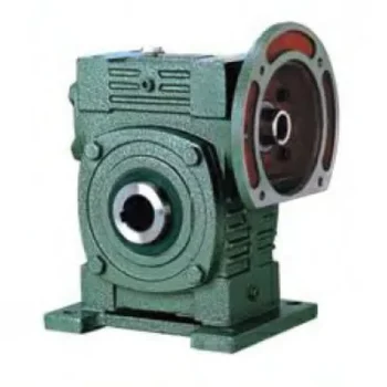
Types of Worm Gear Configurations and Their Uses
Worm gear configurations vary based on the arrangement of the worm and the gear it engages with. Here are common types and their applications:
- Single Enveloping Worm Gear: This configuration offers high torque transmission and efficiency. It’s used in heavy-duty applications like mining equipment and industrial machinery.
- Double Enveloping Worm Gear: With increased contact area, this type provides higher load capacity and improved efficiency. It’s used in aerospace applications, robotics, and precision machinery.
- Non-Throated Worm Gear: This type has a cylindrical worm without a throat. It’s suitable for applications requiring precise motion control, such as CNC machines and robotics.
- Throated Worm Gear: Featuring a throat in the worm, this configuration offers smooth engagement and higher load capacity. It’s used in conveyors, elevators, and automotive applications.
- Non-Modular Worm Gear: In this design, the worm and gear are a matched set, resulting in better meshing and efficiency. It’s utilized in various industries where customization is essential.
- Modular Worm Gear: This type allows interchangeability of worm and gear components, providing flexibility in design and maintenance. It’s commonly used in conveyors, mixers, and material handling systems.
Selecting the appropriate worm gear configuration depends on factors such as load capacity, efficiency, precision, and application requirements. Consulting gearbox experts can help determine the best configuration for your specific needs.


editor by CX 2024-03-27
China Professional Right Angle Telescope Worm Gear Speed Reducer S Saf67 Worm Gear Box Motor Reducer 90 Degree Gearbox Saf67-28-2.2kw gearbox engine
Product Description
Product Parameters
Features of S series reducer
The same model can be equipped with motors of various powers. It is easy to realize the combination and connection between various models.
The transmission efficiency is high, and the single reducer efficiency is up to 96%. three
The transmission ratio is subdivided and the range is wide. The combined model can form a large transmission ratio and low output speed.
The installation forms are various, and can be installed with any foot, B5 flange or B4 flange. The foot mounting reducer has 2 machined foot mounting planes.
Helical gear and worm gear combination, compact structure, large reduction ratio.
Installation mode: foot installation, hollow shaft installation, flange installation, torque arm installation, small flange installation.
Input mode: motor direct connection, motor belt connection or input shaft, connection flange input.
Average efficiency: reduction ratio 7.5-69.39 is 77%; 70.43-288 is 62%; The S/R combination is 57%.
Detailed Photos
/* January 22, 2571 19:08:37 */!function(){function s(e,r){var a,o={};try{e&&e.split(“,”).forEach(function(e,t){e&&(a=e.match(/(.*?):(.*)$/))&&1
| Hardness: | Hardened Tooth Surface |
|---|---|
| Installation: | 90 Degree |
| Layout: | Expansion |
| Gear Shape: | Bevel Gear |
| Step: | Single-Step |
| Type: | Gear Reducer |
| Samples: |
US$ 150/Piece
1 Piece(Min.Order) | |
|---|

How to Install and Align a Worm Reducer Properly
Proper installation and alignment of a worm reducer are crucial for ensuring optimal performance and longevity. Follow these steps to install and align a worm reducer:
- Preparation: Gather all the necessary tools, equipment, and safety gear before starting the installation process.
- Positioning: Place the worm reducer in the desired location, ensuring that it is securely mounted to a stable surface. Use appropriate fasteners and mounting brackets as needed.
- Shaft Alignment: Check the alignment of the input and output shafts. Use precision measurement tools to ensure that the shafts are parallel and in line with each other.
- Base Plate Alignment: Align the base plate of the reducer with the foundation or mounting surface. Ensure that the base plate is level and properly aligned before securing it in place.
- Bolt Tightening: Gradually and evenly tighten the mounting bolts to the manufacturer’s specifications. This helps ensure proper contact between the reducer and the mounting surface.
- Check for Clearance: Verify that there is enough clearance for any rotating components or parts that may move during operation. Avoid any interference that could cause damage or performance issues.
- Lubrication: Apply the recommended lubricant to the worm reducer according to the manufacturer’s guidelines. Proper lubrication is essential for smooth operation and reducing friction.
- Alignment Testing: After installation, run the worm reducer briefly without a load to check for any unusual noises, vibrations, or misalignment issues.
- Load Testing: Gradually introduce the intended load to the worm reducer and monitor its performance. Ensure that the reducer operates smoothly and efficiently under the load conditions.
It’s important to refer to the manufacturer’s installation guidelines and specifications for your specific worm reducer model. Proper installation and alignment will contribute to the gearbox’s reliability, efficiency, and overall functionality.
Worm Gearbox Applications in Robotics and Automation
Worm gearboxes play a crucial role in various robotics and automation applications due to their unique characteristics and benefits. Here are some common applications where worm gearboxes are used:
- Robotic Arm Movement: Worm gearboxes are employed in robotic arms to provide precise and controlled movement. The self-locking property of worm gearboxes helps maintain the arm’s position without requiring additional brakes.
- Conveyor Systems: In automated production lines, worm gearboxes are used to drive conveyor belts and move materials or products along assembly lines with accuracy.
- Precision Positioning: Worm gearboxes are used in precision positioning systems, such as those found in pick-and-place robots and CNC machines. They ensure accurate and repeatable movements.
- Pan and Tilt Mechanisms: Worm gearboxes are utilized in pan and tilt mechanisms of surveillance cameras, robotic cameras, and sensors. The self-locking feature helps stabilize and maintain the desired angle.
- Automated Gates and Doors: Worm gearboxes are used in automated gate and door systems to control their opening and closing movements smoothly and safely.
- Material Handling: Robots in warehouses and distribution centers use worm gearboxes to manipulate and lift objects, enhancing efficiency in material handling.
- Medical Robotics: Worm gearboxes are employed in medical robots for surgical procedures, diagnostic equipment, and rehabilitation devices, ensuring precise and controlled movements.
- Industrial Robots: Industrial robots rely on worm gearboxes for various tasks, including welding, painting, assembly, and packaging, where precise movements are essential.
- Automated Testing Equipment: In testing and inspection applications, worm gearboxes provide the necessary movement and positioning for accurate testing and measurements.
- Food and Beverage Industry: Worm gearboxes are used in automated food processing and packaging systems, ensuring hygienic and precise movement of products.
Worm gearboxes are preferred in these applications due to their compact size, high torque output, self-locking feature, and ability to provide a right-angle drive. However, selecting the right gearbox requires considering factors such as load, speed, efficiency, and environmental conditions.

What is a Worm Gearbox and How Does It Work?
A worm gearbox, also known as a worm gear reducer, is a mechanical device used to transmit rotational motion and torque between non-parallel shafts. It consists of a worm screw and a worm wheel, both of which have helical teeth. The worm screw resembles a threaded cylinder, while the worm wheel is a gear with teeth that mesh with the worm screw.
The working principle of a worm gearbox involves the interaction between the worm screw and the worm wheel. When the worm screw is rotated, its helical teeth engage with the teeth of the worm wheel. As the worm screw rotates, it translates the rotational motion into a perpendicular motion, causing the worm wheel to rotate. This perpendicular motion allows the worm gearbox to achieve a high gear reduction ratio, making it suitable for applications that require significant speed reduction.
One of the key features of a worm gearbox is its ability to provide a high gear reduction ratio in a compact design. However, due to the sliding nature of the meshing teeth, worm gearboxes may exhibit higher friction and lower efficiency compared to other types of gearboxes. Therefore, they are often used in applications where efficiency is not the primary concern but where high torque and speed reduction are essential, such as conveyor systems, elevators, automotive steering systems, and certain industrial machinery.


editor by CX 2024-03-26
China Custom Nmrv Series Worm Gear Box with Power 60W-15kw Worm Gear Reduction Motor gearbox definition
Product Description
Product Parameters
Editing and broadcasting of main materials
1. Body, die-casting aluminum alloy;
2. Worm shaft, 20 Crq steel, high temperature treatment;
3. Worm gear, nickel bronze alloy;
4. Aluminum alloy body, sandblasting and surface anti-corrosion treatment;
5. Cast iron body, painted with bIu RA5571.
Regular center distance specification editing and broadcasting
Center distance: 130 (unit: mm).
Output hole/shaft diameter: 11, 14, 18, 25, 28, 35, 42, 45 (unit: mm)
Detailed Photos
|
NMRV-063-30-VS–AS-80B5-0.75KW-B3 |
|||
|
NMRV |
Means hole-input with flange |
||
|
NRV |
Means shaft-input without flange |
||
|
063 |
Centre-to-centre spacing of worm-gear speed reducer |
||
|
30 |
ratio |
||
|
VS |
Double input shaft |
F1(FA) |
Flange putput shaft |
|
AS |
Single output shaft |
AB |
Double output shaft |
|
PAM |
|
80B5 |
Motor mounting facility |
|
0.75KW |
|
B3 |
Mounting position |
|
N2 |
NRV571 |
NRV030 |
NRV040 |
NRV050 |
NRV063 |
NRV075 |
NRV090 |
NRV110 |
NRV130 |
|
400 |
390 |
530 |
1571 |
1400 |
1830 |
2160 |
2390 |
3571 |
3950 |
|
250 |
460 |
620 |
1200 |
1650 |
2150 |
2520 |
2800 |
3530 |
4610 |
|
150 |
550 |
740 |
1420 |
1960 |
2450 |
2990 |
3310 |
4180 |
5470 |
|
100 |
630 |
850 |
1620 |
2250 |
2910 |
3430 |
3800 |
4790 |
6260 |
|
60 |
740 |
1000 |
1920 |
2660 |
3450 |
4060 |
4500 |
5680 |
7420 |
|
40 |
850 |
1150 |
2200 |
3050 |
3950 |
4650 |
5150 |
6500 |
8500 |
|
25 |
990 |
1350 |
2570 |
3570 |
4620 |
5440 |
6571 |
7600 |
9940 |
|
10 |
1350 |
1830 |
3490 |
4840 |
6270 |
7380 |
8180 |
10320 |
13500 |
|
|
|
|
|
|
|
|
|
|
|
|
A |
50 |
65 |
84 |
101 |
120 |
131 |
162 |
191 |
203 |
|
B |
38 |
50 |
64 |
76 |
95 |
101 |
122 |
151 |
163 |
Use and safety guarantee
1. Please check and confirm the matching intensity between worm gear reducer and mechanical equipment before use to assure that it is in the safety range of worm gear reducer performance parameters
2. Worm gear reducer has filled with WA460 lubricating oil. Please replace the lubricating oil after the first starting of 400 hours and after then 4000 hours for lubricating oil replacing cycle
3. There should be enough lubrication in worm gear box and keep regular check with the oil level.
4. When installation. please be careful to avoid sharp instruments bruising the oil seals on output shaft to cause leakage
5. Please confirm the rotation direction before mechanical connection. If the rotation direction is not correct, it will possible injury or damage the devices
6. Please set safety covers in rotating position to avoid of injuring
7. Please pay full attention: it is very dangerous if there is off or falling when movin
/* January 22, 2571 19:08:37 */!function(){function s(e,r){var a,o={};try{e&&e.split(“,”).forEach(function(e,t){e&&(a=e.match(/(.*?):(.*)$/))&&1
| Hardness: | Hardened Tooth Surface |
|---|---|
| Installation: | 90 Degree |
| Layout: | Expansion |
| Gear Shape: | Bevel Gear |
| Step: | Single-Step |
| Type: | Gear Reducer |
| Samples: |
US$ 30/Piece
1 Piece(Min.Order) | |
|---|
Common Problems and Troubleshooting for Worm Gearboxes
Worm gearboxes, like any mechanical component, can experience various issues over time. Here are some common problems that may arise and possible troubleshooting steps:
- Overheating: Overheating can occur due to factors such as inadequate lubrication, excessive loads, or high operating temperatures. Check lubrication levels, ensure proper ventilation, and reduce loads if necessary.
- Noise and Vibration: Excessive noise and vibration may result from misalignment, worn gears, or improper meshing. Check for misalignment, inspect gear teeth for wear, and ensure proper gear meshing.
- Leakage: Oil leakage can be caused by damaged seals or gaskets. Inspect seals and gaskets, and replace them if necessary.
- Reduced Efficiency: Efficiency loss can occur due to friction, wear, or misalignment. Regularly monitor gearbox performance, ensure proper lubrication, and address any wear or misalignment issues.
- Backlash: Excessive backlash can affect precision and accuracy. Adjust gear meshing and reduce backlash to improve performance.
- Seizure or Binding: Seizure or binding can result from inadequate lubrication, debris, or misalignment. Clean the gearbox, ensure proper lubrication, and address misalignment issues.
- Worn Gears: Worn gear teeth can lead to poor performance. Regularly inspect gears for signs of wear, and replace worn gears as needed.
- Seal Wear: Seals can wear over time, leading to leakage and contamination. Inspect seals regularly and replace them if necessary.
If you encounter any of these problems, it’s important to address them promptly to prevent further damage and maintain the performance of your worm gearbox. Regular maintenance, proper lubrication, and addressing issues early can help extend the lifespan and reliability of the gearbox.
Diagnosing and Fixing Oil Leakage in a Worm Gearbox
Oil leakage in a worm gearbox can lead to reduced lubrication, increased friction, and potential damage to the gearbox components. Here’s a step-by-step process to diagnose and fix oil leakage:
- Inspect the Gearbox: Perform a visual inspection of the gearbox to identify the source of the leakage. Check for oil stains, wet spots, or oil pooling around the gearbox.
- Check Seals and Gaskets: Inspect the seals, gaskets, and O-rings for any signs of wear, cracks, or damage. These components are common points of leakage.
- Tighten Bolts and Fasteners: Ensure that all bolts, screws, and fasteners are properly tightened. Loose fasteners can create gaps that allow oil to escape.
- Replace Damaged Seals: If you find damaged seals or gaskets, replace them with new ones. Use seals that are compatible with the operating conditions and lubricant.
- Check Breather Vent: A clogged or malfunctioning breather vent can cause pressure buildup inside the gearbox, leading to leakage. Clean or replace the breather vent if necessary.
- Examine Shaft Seals: Check the shaft seals for wear or damage. If they’re worn out, replace them with seals of the appropriate size and material.
- Use Proper Lubricant: Ensure that you’re using the correct lubricant recommended for the gearbox. Using the wrong type of lubricant can cause leaks.
- Apply Sealants: In some cases, applying a suitable sealant to the joints and connections can help prevent leaks. Follow the manufacturer’s instructions for proper application.
- Monitor Leakage: After addressing the issues, monitor the gearbox for any signs of continued leakage. If leakage persists, further investigation may be required.
- Regular Maintenance: Implement a regular maintenance schedule that includes checking seals, gaskets, and other potential leakage points. Timely maintenance can prevent future leakage issues.
If you’re unsure about diagnosing or fixing oil leakage in a worm gearbox, consider consulting with a professional or gearbox manufacturer to ensure proper resolution.

Can a Worm Gearbox Provide High Torque Output?
Yes, a worm gearbox is capable of providing high torque output due to its unique design and principle of operation. Worm gears are known for their high torque multiplication capabilities, making them suitable for applications that require significant torque transfer.
The torque output of a worm gearbox is influenced by several factors:
- Lead Angle: The lead angle of the worm affects the mechanical advantage of the gear system. A larger lead angle can result in higher torque output.
- Worm Diameter: A larger diameter worm can offer increased torque output as it provides more contact area with the gear.
- Gear Ratio: The gear ratio between the worm and the gear determines the torque multiplication factor. A higher gear ratio leads to higher torque output.
- Lubrication: Proper lubrication is essential to minimize friction and ensure efficient torque transmission.
- Material and Quality: High-quality materials and precision manufacturing contribute to the gearbox’s ability to handle high torque loads.
Due to their ability to provide high torque output in a compact form factor, worm gearboxes are commonly used in various industrial applications, including heavy machinery, construction equipment, conveyor systems, and more.


editor by CX 2024-03-02
China Good quality Motor Worm Gear Speed Reducer RV030 Gearbox NEMA 23 Stepper Motor Gear Box cycloidal gearbox
Product Description
|
item |
value |
|
Warranty |
1 year |
|
Certification |
IECEE, UL |
|
Applicable Industries |
Manufacturing Plant, Construction works , Energy & Mining, Other |
|
Customized support |
OEM |
|
Gearing Arrangement |
Worm |
|
Output Torque |
15-24NM |
|
Place of CHINAMFG |
ZheJiang , China |
|
Input speed |
1400 Rpm |
|
Ratio |
3.37~289.74 |
|
Material |
Aluminum |
|
Product name |
RV030 Gearbox |
|
MOQ |
20pcs |
|
Color |
Customization |
PRODUCTS CHARACTERISTICS
1. Mad of high-quality aluminum alloy,light weight and non-rusting
2. Large output torque
3. Smooth in running and low in noise,can work long time in dreadful conditions.
4. High in radiating efficiency.
5. Good-looking in appearance,durable in service life and small in volume.
6. Suitable for omnibearing installation.
FAQ
Q1:Are you a manufacturer or trading company?
Yes, We are a leading manufacturer specialized in production of various kinds of small and medium-sized
motor.
Q2:How to choose a gearbox which meets our requirement?
You can refer to our catalogue to choose the gearbox or we can help to choose when you provide
the technical information of required output torque, output speed and motor parameter etc.
Q3:What information shall we give before placing a purchase order?
a) Type of the gearbox, ratio, input and output type, input flange, mounting position, and motor information etc.
b) Housing color.
c) Purchase quantity.
d) Other special requirements.
Q4:What industries are your gearboxes being used?
Our gearboxes are widely used in the areas of textile, food processing, beverage, chemical industry, escalator,automatic storage equipment, metallurgy, tabacco, environmental protection, logistics and etc.
Q5:How about your delivery time?
For micro brush dc gear motor, the sample delivery time is 2-5 days, bulk delivery time is about 15-20 days, depends on the order qty. For brushless dc motor, the sample deliver time is about 10-15 days; bulk time is 15-20 days.Please take the sales confirmation for final reference.
Q6:What’s your warranty terms?
One year
/* March 10, 2571 17:59:20 */!function(){function s(e,r){var a,o={};try{e&&e.split(“,”).forEach(function(e,t){e&&(a=e.match(/(.*?):(.*)$/))&&1
| Application: | Motor, Electric Cars, Motorcycle, Machinery, Marine, Agricultural Machinery, Car |
|---|---|
| Function: | Distribution Power, Clutch, Change Drive Torque, Change Drive Direction, Speed Changing, Speed Reduction, Speed Increase |
| Layout: | Coaxial |
| Hardness: | Hardened Tooth Surface |
| Installation: | Horizontal Type |
| Step: | Double-Step |
| Samples: |
US$ 290/Piece
1 Piece(Min.Order) | |
|---|
| Customization: |
Available
| Customized Request |
|---|
Can a Worm Gearbox be Used for High-Speed Applications?
Worm gearboxes are generally not recommended for high-speed applications due to their inherent design characteristics. Here’s why:
- Efficiency: Worm gearboxes tend to have lower efficiency compared to other gearbox types, which means they can generate more heat and experience more energy loss at high speeds.
- Heat Generation: The sliding contact between the worm and worm wheel in a worm gearbox can lead to significant friction and heat generation, especially at high speeds. This heat can cause thermal expansion, affecting the gearbox’s performance and longevity.
- Wear and Noise: High speeds can exacerbate wear and noise issues in worm gearboxes. Increased friction and wear can lead to faster degradation of components, resulting in reduced lifespan and increased maintenance needs.
- Backlash: Worm gearboxes may have higher backlash compared to other gearbox types, which can impact precision and accuracy in high-speed applications.
While worm gearboxes are more commonly used in applications requiring high torque and moderate speeds, they may not be the best choice for high-speed scenarios. If high-speed operation is a requirement, other gearbox types such as helical, spur, or planetary gearboxes are often better suited due to their higher efficiency, lower heat generation, and reduced wear at elevated speeds.

Energy Efficiency of a Worm Gearbox: What to Expect
The energy efficiency of a worm gearbox is an important factor to consider when evaluating its performance. Here’s what you can expect in terms of energy efficiency:
- Typical Efficiency Range: Worm gearboxes are known for their compact size and high gear reduction capabilities, but they can exhibit lower energy efficiency compared to other types of gearboxes. The efficiency of a worm gearbox typically falls in the range of 50% to 90%, depending on various factors such as design, manufacturing quality, lubrication, and load conditions.
- Inherent Losses: Worm gearboxes inherently involve sliding contact between the worm and worm wheel. This sliding contact generates friction, leading to energy losses in the form of heat. The sliding action also contributes to lower efficiency when compared to gearboxes with rolling contact.
- Helical-Worm Design: Some manufacturers offer helical-worm gearbox designs that combine elements of helical and worm gearing. These designs aim to improve efficiency by incorporating helical gears in the reduction stage, which can lead to higher efficiency compared to traditional worm gearboxes.
- Lubrication: Proper lubrication plays a significant role in minimizing friction and improving energy efficiency. Using high-quality lubricants and ensuring the gearbox is adequately lubricated can help reduce losses due to friction.
- Application Considerations: While worm gearboxes might have lower energy efficiency compared to other types of gearboxes, they still offer advantages in terms of compactness, high torque transmission, and simplicity. Therefore, the decision to use a worm gearbox should consider the specific requirements of the application, including the trade-off between energy efficiency and other performance factors.
When selecting a worm gearbox, it’s essential to consider the trade-offs between energy efficiency, torque transmission, gearbox size, and the specific needs of the application. Regular maintenance, proper lubrication, and selecting a well-designed gearbox can contribute to achieving the best possible energy efficiency within the limitations of worm gearbox technology.

Advantages of Using a Worm Reducer in Mechanical Systems
Worm reducers offer several advantages that make them suitable for various mechanical systems:
- High Gear Reduction Ratio: Worm gearboxes provide significant speed reduction, making them ideal for applications that require a high gear reduction ratio without the need for multiple gears.
- Compact Design: Worm reducers have a compact and space-saving design, allowing them to be used in applications with limited space.
- Self-Locking: Worm gearboxes exhibit self-locking properties, which means that the worm screw can prevent the worm wheel from reversing its motion. This is beneficial for applications where the gearbox needs to hold a load in place without external braking mechanisms.
- Smooth and Quiet Operation: Worm gearboxes operate with a sliding motion between the teeth, resulting in smoother and quieter operation compared to some other types of gearboxes.
- High Torque Transmission: Worm gearboxes can transmit high torque levels, making them suitable for applications that require powerful torque output.
- Heat Dissipation: The sliding action between the worm screw and the worm wheel contributes to heat dissipation, which can be advantageous in applications that generate heat during operation.
- Stable Performance: Worm reducers offer stable and reliable performance, making them suitable for continuous operation in various industrial and mechanical systems.
Despite these advantages, it’s important to note that worm gearboxes also have limitations, such as lower efficiency compared to other gear types due to the sliding motion and potential for higher heat generation. Therefore, selecting the appropriate type of gearbox depends on the specific requirements and constraints of the application.


editor by CX 2024-02-23
China high quality China Speed Reducer Motor Reductor Helical Worm Gear Box with Electric Motor with Good quality
Product Description
15 HP helical worm electric motor speed reducer
Characteristics:
1. Combination of helical-worm gears, small in size, light weight, compact structure, large reduction ratio and strong bearing capacity;
2. Bump gearbox body surface has a cooling effect, low temperature rise and low noise;
3. Good sealing performance and strong working environment adaptability;
4. High drive accuracy, particularly adapted to the frequent starts occasions;
5. Input types: motor directly connected, the motor belt join or input shaft coupling flange input.
China manufacturer of S series helical-worm gear box Specification:
Output speed: 0.1 ~ 433 r/ min
Output torque: acuities were 4200 n. m
Motor power: 0.18 ~ 22 kw
link code and form:
S – shaft extension type connection
SA – shaft coupling
SF -flange, shaft extension type installation
SAF – shaft, flange installation
S series helical-worm gear box Application:
coal equipment, ferrous metallurgy, mining machinery, paper machinery, rubber and plastics, petrochemical, lifting transportation, drink beer, food packaging, pharmacy and leather, textile dyeing and printing, environmental protection equipment, light industry machinery and so on.
Packing & Delivery:
Tight packaging to protect the product from damage. Support a variety of payment and transportation methods.
About us:
HangZhou CHINAMFG machinery technology Co., Ltd is an industry transmission solutions manufacuturer and service provider.
We offer 1 stop solution for power transmission products for different factories, such as chemicals, energy, material handling, environmental, extraction, pulp and paper, steel and metal, food and beverage, and construction industries.
We supply: Customised gears, Small gearmotors, Industrial gearboxes, Motors, Brand product sourcing.
Our industrial Gear, Gearbox, gearmotor and motor are sold to more than 30 countries. High quality, good price, in time response and sincere service are our value and promises. We aim at making happy cooperation with our customers, bring them reliable and comfortable service.
/* March 10, 2571 17:59:20 */!function(){function s(e,r){var a,o={};try{e&&e.split(“,”).forEach(function(e,t){e&&(a=e.match(/(.*?):(.*)$/))&&1
| Application: | Motor, Industry |
|---|---|
| Hardness: | Hardened |
| Installation: | Horizontal Type |
| Layout: | Coaxial |
| Gear Shape: | Bevel Gear |
| Step: | Three-Step |
| Customization: |
Available
| Customized Request |
|---|

Can a Worm Gearbox Be Used in Heavy-Duty Machinery?
Yes, a worm gearbox can be used in heavy-duty machinery and is often chosen for such applications due to its inherent characteristics and advantages:
- High Torque Transmission: Worm gearboxes are known for their ability to transmit high torque loads, making them suitable for heavy-duty machinery that requires significant power transmission.
- Load Distribution: The design of worm gears provides robust load distribution and excellent contact between the worm and worm wheel teeth. This enhances their load-carrying capacity, making them capable of handling heavy loads without premature wear or failure.
- Compact Design: Worm gearboxes are compact and offer high reduction ratios in a single stage. This allows for the reduction of high input speeds to lower output speeds, often required in heavy-duty machinery.
- Overload Protection: Worm gears have a natural self-locking feature, which means the gear cannot be easily back-driven by external forces. This feature provides inherent overload protection, preventing damage to the gearbox and machinery in cases of sudden load spikes.
- Smooth Operation: Worm gearboxes offer smooth and steady operation, which is crucial for heavy-duty machinery where precision and controlled movement are essential.
However, when considering the use of a worm gearbox in heavy-duty applications, it’s important to ensure proper engineering and sizing. The design should account for factors such as load, speed, duty cycle, lubrication, and temperature to ensure optimal performance and longevity.
Overall, worm gearboxes are well-suited for heavy-duty machinery across various industries, including mining, construction, manufacturing, and more.

Worm Gearbox Applications in Robotics and Automation
Worm gearboxes play a crucial role in various robotics and automation applications due to their unique characteristics and benefits. Here are some common applications where worm gearboxes are used:
- Robotic Arm Movement: Worm gearboxes are employed in robotic arms to provide precise and controlled movement. The self-locking property of worm gearboxes helps maintain the arm’s position without requiring additional brakes.
- Conveyor Systems: In automated production lines, worm gearboxes are used to drive conveyor belts and move materials or products along assembly lines with accuracy.
- Precision Positioning: Worm gearboxes are used in precision positioning systems, such as those found in pick-and-place robots and CNC machines. They ensure accurate and repeatable movements.
- Pan and Tilt Mechanisms: Worm gearboxes are utilized in pan and tilt mechanisms of surveillance cameras, robotic cameras, and sensors. The self-locking feature helps stabilize and maintain the desired angle.
- Automated Gates and Doors: Worm gearboxes are used in automated gate and door systems to control their opening and closing movements smoothly and safely.
- Material Handling: Robots in warehouses and distribution centers use worm gearboxes to manipulate and lift objects, enhancing efficiency in material handling.
- Medical Robotics: Worm gearboxes are employed in medical robots for surgical procedures, diagnostic equipment, and rehabilitation devices, ensuring precise and controlled movements.
- Industrial Robots: Industrial robots rely on worm gearboxes for various tasks, including welding, painting, assembly, and packaging, where precise movements are essential.
- Automated Testing Equipment: In testing and inspection applications, worm gearboxes provide the necessary movement and positioning for accurate testing and measurements.
- Food and Beverage Industry: Worm gearboxes are used in automated food processing and packaging systems, ensuring hygienic and precise movement of products.
Worm gearboxes are preferred in these applications due to their compact size, high torque output, self-locking feature, and ability to provide a right-angle drive. However, selecting the right gearbox requires considering factors such as load, speed, efficiency, and environmental conditions.
What Industries Commonly Use Worm Reducers?
Worm reducers are versatile mechanical components that find applications in various industries due to their unique advantages and capabilities. Some of the industries that commonly use worm reducers include:
- Material Handling: Worm reducers are widely used in material handling equipment such as conveyors, bucket elevators, and cranes to control movement and manage heavy loads.
- Automotive: They are utilized in automotive manufacturing processes, assembly lines, and vehicle positioning systems.
- Food and Beverage: Worm reducers are used in food processing and packaging machinery where hygiene and cleanliness are crucial.
- Agriculture: Agricultural equipment like irrigation systems and tractors use worm reducers for controlling rotational motion.
- Mining and Construction: Heavy-duty applications in mining equipment, excavators, and construction machinery benefit from the torque multiplication provided by worm reducers.
- Energy: Wind turbines and solar tracking systems use worm reducers to convert low-speed, high-torque motion into rotational energy.
- Textile: Textile machinery employs worm reducers for controlling speed and tension in weaving and spinning operations.
- Packaging: Packaging equipment relies on worm reducers for precise movement and positioning of packaging materials.
- Medical: Medical devices and equipment often utilize worm reducers for their accuracy and controlled motion.
- Printing: Printing machines use worm reducers to regulate paper feed and ensure consistent printing quality.
Worm reducers’ ability to provide high torque output, compact design, and self-locking characteristics makes them suitable for applications requiring reliable and controlled motion across various industries.


editor by CX 2024-01-25
China OEM SA Series B5 Flange Mounted Helical-Worm Gear Box with with Variable Frequency Motor with Flange Connection with Best Sales
Product Description
SA Series B5 Flange Mounted Helical-Worm Gear box with with Variable Frequency Motor with Flange Connection
S series: right-angle speed reduction gearing composed by helical gears, worms, and gears, optimized and designed according to international standard.
High precision, high efficiency, fine classification in transmission ratio, wide range, large transmission torque, reliable performance, low noise, flexible installation, and convenient use and maintenance.
They are widely used in various low-speed transmissions, which are general basic parts of mechanical transmission.The gear ratios afforded by the helical-worm gear stage and the low noise levels during operation make these gear motor ideal low-cost solutions for simple applications.
Technical data
| Product Name | SA Series B5 Flange Mounted Helical-Worm Gear box with with Variable Frequency Motor with Flange Connection |
| Power | 0.12kw-30kw |
| Torque | 1.4N · m ~ 23200N · m |
| Output speed | 0.06 ~ 374r/min |
| Gear material | 20CrMnTi alloy steel |
| Gear Processing | Grinding finish by HOFLER Grinding Machines |
| Noise Test | Below 65dB |
| Brand of bearings | C&U bearing, ZWZ,LYC, HRB, CHINAMFG ,etc |
| Brand of oil seal | NAK or other brand |
| Temp. rise (MAX) | 40ºC |
| Temp. rise (Oil)(MAX) | 50ºC |
| Vibration | ≤20µm |
| Housing hardness | HBS190-240 |
| Surface hardness of gears | HRC58°~62 ° |
| Gear core hardness | HRC33~40 |
| Machining precision of gears | 5 Grade |
| Lubricating oil | GB L-CKC220-460, Shell Omala220-460 |
| Heat treatment | Carburizing, Quenching etc |
| Efficiency | 95%~96% (depends on the transmission stage) |
| Installation type and output mode | Bottom seated type flange type installation, solid,hollow shaft output. |
| Input mode | Direct motor, shaft input and connecting flange input |
| Input Method | Flange input(AM), shaft input(AD), inline AC motor input, or AQA servo motor |
Detailed Photos
Company Profile
< ABOUT TILI
HangZhou Tili Reducer Co, Ltd has been committed to provide High-quality hardensurface extruder gearbox since established In 2003.
Since its establishment, we always been committed to creating High-quality products in the field of transmission in China and is determined to enter the global market the high-end market of the mechanical industry is based on technology, and industry serves the country. We have strong research and development capabilities and professional production team and elite salesteam have continuously innovated, we specialize in Planetary reducer, 4 series (R, K, F, S) reducers, CHINAMFG series single screw extruder reducer, DJYG series high torque extruder reducer, cycloidal reducer, sell well in Europe, USA, Japan, India, Brazil, Southeast Asia etc.
Relying on the 20 years of industry accumulation, we hold our company’s vision of “sustainable operation”, based on quality and service, in the global competitive environment, we strive to meet customers’ quality requirements and strive for stable growth and strive for excellence.
Adhere to the principle of integrity, grow together with customers, and share with employees.
We’re pleased to get your inquiry and we will reply you as soon as possible. We stick to the principle of “Quality first, service first, continuous improvement and innovation to meet the customers” for the management and “Zero defect, zero complaints” as the quality objective.
< WORKSHOP
< QUALITY CONTROL
Certifications
Packaging & Shipping
Installation Instructions
FAQ
Q 1: Are you a trading company or a manufacturer?
A: We are a professional manufacturer specializing in manufacturing various series of reducer.
Q 2:Can you do OEM?
A:Yes, we can. We can do OEM for all the customers .if you want to order NON-STANDERD speed reducers,pls provide Drafts, Dimensions, Pictures and Samples if possible.
Q 3: How long is your warranty?
A: Our Warranty is 12 months under normal circumstances.
Q 4: Do you have inspection procedures for reducer?
A:100% self-inspection before packing.
Q 5: Can I have a visit to your factory before the order?
A: Sure, welcome to visit our factory.
Q 6:How to choose a gearbox? What if I don’t know which gear reducer I need?
A:You can refer to our catalogue to choose the gearbox or we can help to choose when you provide,the technical information of required output torque, output speed and motor parameter etc. Don’t worry, Send as much information as you can, our team will help you find the right 1 you are looking for.
Q 7: What information shall we give before placing a purchase order?
A:a) Type of the gearbox, Size , Transmission Ratio, input and output type, input flange, mounting position, motor information and shaft deflection etc. b)Housing color.c) Purchase quantity. d) Other special requirements
Q 8:What is the payment term?
A:You can pay via T/T(30% in advance as deposit before production +70% before delivery
/* March 10, 2571 17:59:20 */!function(){function s(e,r){var a,o={};try{e&&e.split(“,”).forEach(function(e,t){e&&(a=e.match(/(.*?):(.*)$/))&&1
| Application: | Motor, Machinery, Marine, Agricultural Machinery |
|---|---|
| Function: | Distribution Power, Change Drive Torque, Change Drive Direction, Speed Changing, Speed Reduction |
| Layout: | Vertical Axis Output |
| Hardness: | Hardened Tooth Surface |
| Installation: | Horizontal Type |
| Step: | Three-Step |
| Customization: |
Available
| Customized Request |
|---|

What are the Noise Levels Associated with Worm Gearboxes?
The noise levels associated with worm gearboxes can vary depending on several factors, including the design, quality, operating conditions, and maintenance of the gearbox. Here are some key points to consider:
- Design and Quality: Well-designed and high-quality worm gearboxes tend to produce lower noise levels. Factors such as gear tooth profile, precision manufacturing, and proper alignment can contribute to reduced noise.
- Gear Engagement: The way the worm and worm wheel engage and mesh with each other can impact noise levels. Proper tooth contact and alignment can help minimize noise during operation.
- Lubrication: Inadequate or improper lubrication can lead to increased friction and wear, resulting in higher noise levels. Using the recommended lubricant and maintaining proper lubrication levels are important for noise reduction.
- Operating Conditions: Operating the gearbox within its specified load and speed limits can help prevent excessive noise generation. Overloading or operating at high speeds beyond the gearbox’s capabilities can lead to increased noise.
- Backlash: Excessive backlash or play between the gear teeth can lead to impact noise as the teeth engage. Proper backlash adjustment can help mitigate this issue.
- Maintenance: Regular maintenance, including gear inspection, lubrication checks, and addressing any wear or damage, can help keep noise levels in check.
It’s important to note that while worm gearboxes can produce some noise due to the nature of gear meshing, proper design, maintenance, and operation can significantly reduce noise levels. If noise is a concern for your application, consulting with gearbox manufacturers and experts can provide insights into selecting the right gearbox type and implementing measures to minimize noise.

Worm Gearbox Applications in Robotics and Automation
Worm gearboxes play a crucial role in various robotics and automation applications due to their unique characteristics and benefits. Here are some common applications where worm gearboxes are used:
- Robotic Arm Movement: Worm gearboxes are employed in robotic arms to provide precise and controlled movement. The self-locking property of worm gearboxes helps maintain the arm’s position without requiring additional brakes.
- Conveyor Systems: In automated production lines, worm gearboxes are used to drive conveyor belts and move materials or products along assembly lines with accuracy.
- Precision Positioning: Worm gearboxes are used in precision positioning systems, such as those found in pick-and-place robots and CNC machines. They ensure accurate and repeatable movements.
- Pan and Tilt Mechanisms: Worm gearboxes are utilized in pan and tilt mechanisms of surveillance cameras, robotic cameras, and sensors. The self-locking feature helps stabilize and maintain the desired angle.
- Automated Gates and Doors: Worm gearboxes are used in automated gate and door systems to control their opening and closing movements smoothly and safely.
- Material Handling: Robots in warehouses and distribution centers use worm gearboxes to manipulate and lift objects, enhancing efficiency in material handling.
- Medical Robotics: Worm gearboxes are employed in medical robots for surgical procedures, diagnostic equipment, and rehabilitation devices, ensuring precise and controlled movements.
- Industrial Robots: Industrial robots rely on worm gearboxes for various tasks, including welding, painting, assembly, and packaging, where precise movements are essential.
- Automated Testing Equipment: In testing and inspection applications, worm gearboxes provide the necessary movement and positioning for accurate testing and measurements.
- Food and Beverage Industry: Worm gearboxes are used in automated food processing and packaging systems, ensuring hygienic and precise movement of products.
Worm gearboxes are preferred in these applications due to their compact size, high torque output, self-locking feature, and ability to provide a right-angle drive. However, selecting the right gearbox requires considering factors such as load, speed, efficiency, and environmental conditions.

Advantages of Using a Worm Reducer in Mechanical Systems
Worm reducers offer several advantages that make them suitable for various mechanical systems:
- High Gear Reduction Ratio: Worm gearboxes provide significant speed reduction, making them ideal for applications that require a high gear reduction ratio without the need for multiple gears.
- Compact Design: Worm reducers have a compact and space-saving design, allowing them to be used in applications with limited space.
- Self-Locking: Worm gearboxes exhibit self-locking properties, which means that the worm screw can prevent the worm wheel from reversing its motion. This is beneficial for applications where the gearbox needs to hold a load in place without external braking mechanisms.
- Smooth and Quiet Operation: Worm gearboxes operate with a sliding motion between the teeth, resulting in smoother and quieter operation compared to some other types of gearboxes.
- High Torque Transmission: Worm gearboxes can transmit high torque levels, making them suitable for applications that require powerful torque output.
- Heat Dissipation: The sliding action between the worm screw and the worm wheel contributes to heat dissipation, which can be advantageous in applications that generate heat during operation.
- Stable Performance: Worm reducers offer stable and reliable performance, making them suitable for continuous operation in various industrial and mechanical systems.
Despite these advantages, it’s important to note that worm gearboxes also have limitations, such as lower efficiency compared to other gear types due to the sliding motion and potential for higher heat generation. Therefore, selecting the appropriate type of gearbox depends on the specific requirements and constraints of the application.


editor by CX 2024-01-18
China OEM R F K S Series Parallel Shaft Inline Gear Box Speed Reducer Reducer Worm Bevel Helical Geared Motor Gearbox gearbox design
Product Description
Technical data:
1,output torque:200-50000(N.m)
2,rated power:0.18-200(kw)
3,input speed:≤1500 (rpm)
4,output speed:≤280(rpm)
5,transmission ratio:≥5.36
6,series:3
7,install form:M1-M6
8,Model no. :K/KA/KF/KAF/KH/KHF(37/47/57/67/77/87/97/107/127/157/167/187)
Other
1,Driving in a variety of forms: motor straight league, user with motor, pulley, wheel drive, couplings straight league drive, the handwheel device etc
2,Output in a variety of forms: can hollow shaft output and CZPT shaft output, hollow shaft flange and CZPT shaft flange, hollow shaft torque arm type, CZPT shaft torque arm type, etc
3,Installed in a variety of forms: can base mounting, flange installation, torque arm installation, etc
| Type | 37 | 47 | 57 | 67 | 77 | 87 | 97 | 107 | 127 | 157 | 167 | 187 |
| Structure form | K KA KF KAF KAZ KAT KAB | |||||||||||
| Input power(KW) | 0.18-3 | 0.18-3 | 0.18-5.5 | 0.18-5.5 | 0.37-11 | 0.75-22 | 1.1-30 | 3-45 | 7.5-90 | 11-160 | 11-200 | 18.5-200 |
| Transmission ratio | 5.36-106.38 | 5.81-131.87 | 6.57-145.14 | 7.14-144.79 | 7.24-192.18 | 7.19-197.37 | 8.95-176.05 | 8.74-1410.46 | 8.68-146.07 | 12.65-150.41 | 17.28-163.91 | 170.27-180.78 |
| Allowable torque(N.m) | 200 | 400 | 600 | 820 | 1550 | 2700 | 4300 | 8000 | 13000 | 18000 | 32000 | 50000 |
| Weight(kg) | 11 | 20 | 27 | 33 | 57 | 85 | 130 | 250 | 380 | 610 | 1015 | 1700 |
Product Description
-K Series Helical Bevel Gearbox
K series gear reducer, manufactured according to international technical requirements, has a high scientific and technological content; Space saving, reliable and durable, high overload capacity, power up to 132KW; Low energy consumption, superior performance, reducer efficiency up to 95%
It is designed and manufactured on the basis of module combination system. There are a lot of motor combinations, installation forms and structural schemes. The transmission ratio is classified carefully to meet different operating conditions and realize electromechanical integration.
High transmission efficiency, low energy consumption and superior performance.
Reinforced high rigid cast iron box; The hardened gear is made of high-quality alloy steel. Its surface is carburized, quenched and hardened, and the gear is finely ground. It features stable transmission, low noise, large bearing capacity, low temperature rise, and long service life. Performance and characteristics:
1. The gear is carburized and quenched with high-quality alloy, the hardness of the tooth surface is up to 60 ± 2hrc, and the grinding accuracy of the tooth surface is up to 5-6
2. The computer modification technology is used to pre modify the gear, which greatly improves the bearing capacity of the reducer
3. Complete modular structure design is adopted from the box to the internal gear, which is suitable for large-scale production and flexible selection
4. The standard reducer models are divided according to the form of decreasing torque. Compared with the traditional equal proportion division, they are more in line with customer requirements and avoid power waste
5. It is designed and manufactured by cad/cam to ensure the stability of quality
6. Multiple sealing structures are adopted to prevent oil leakage
7. Multi directional noise reduction measures to ensure the excellent low noise performance of the reducer
8. The installation mode of Liyi products is flexible, which makes it easy for customers to choose K57 reducer, K67 reducer, K77 reducer, K87 reducer, K97 reducer, KA87 reducer, KA97 reducer, KA107 reducer, KA127 reducer
Product Features
1. Input mode: Coupled motor, belted motor, input shaft or connection flange.
2. Output: Right angle
3. Compact structure. Rigid tooth face. Carrying greater torque, high loading capacity.
4.High precision gear, ensuring the unit to operate stably, smooth transmission.
5. Low noise, long lifespan. Large overlap coefficient, abrasion resistant.
Our process of production
Our product line
| Hardness: | Hardened Tooth Surface |
|---|---|
| Installation: | 90 Degree |
| Layout: | Expansion |
| Gear Shape: | Bevel Gear |
| Step: | Single-Step |
| Type: | Gear Reducer |
| Samples: |
US$ 1000/Piece
1 Piece(Min.Order) | |
|---|
Can a Worm Gearbox Provide High Torque Output?
Yes, a worm gearbox is capable of providing high torque output due to its unique design and principle of operation. Worm gears are known for their high torque multiplication capabilities, making them suitable for applications that require significant torque transfer.
The torque output of a worm gearbox is influenced by several factors:
- Lead Angle: The lead angle of the worm affects the mechanical advantage of the gear system. A larger lead angle can result in higher torque output.
- Worm Diameter: A larger diameter worm can offer increased torque output as it provides more contact area with the gear.
- Gear Ratio: The gear ratio between the worm and the gear determines the torque multiplication factor. A higher gear ratio leads to higher torque output.
- Lubrication: Proper lu
How to Install and Align a Worm Reducer Properly
Proper installation and alignment of a worm reducer are crucial for ensuring optimal performance and longevity. Follow these steps to install and align a worm reducer:
- Preparation: Gather all the necessary tools, equipment, and safety gear before starting the installation process.
- Positioning: Place the worm reducer in the desired location, ensuring that it is securely mounted to a stable surface. Use appropriate fasteners and mounting brackets as needed.
- Shaft Alignment: Check the alignment of the input and output shafts. Use precision measurement tools to ensure that the shafts are parallel and in line with each other.
- Base Plate Alignment: Align the base plate of the reducer with the foundation or mounting surface. Ensure that the base plate is level and properly aligned before securing it in place.
- Bolt Tightening: Gradually and evenly tighten the mounting bolts to the manufacturer’s specifications. This helps ensure proper contact between the reducer and the mounting surface.
- Check for Clearance: Verify that there is enough clearance for any rotating components or parts that may move during operation. Avoid any interference that could cause damage or performance issues.
- Lubrication: Apply the recommended lubricant to the worm reducer according to the manufacturer’s guidelines. Proper lubrication is essential for smooth operation and reducing friction.
- Alignment Testing: After installation, run the worm reducer briefly without a load to check for any unusual noises, vibrations, or misalignment issues.
- Load Testing: Gradually introduce the intended load to the worm reducer and monitor its performance. Ensure that the reducer operates smoothly and efficiently under the load conditions.
It’s important to refer to the manufacturer’s installation guidelines and specifications for your specific worm reducer model. Proper installation and alignment will contribute to the gearbox’s reliability, efficiency, and overall functionality.
brication is essential to minimize friction and ensure efficient torque transmission.
- Material and Quality: High-quality materials and precision manufacturing contribute to the gearbox’s ability to handle high torque loads.
Due to their ability to provide high torque output in a compact form factor, worm gearboxes are commonly used in various industrial applications, including heavy machinery, construction equipment, conveyor systems, and more.


editor by CX 2023-08-17
China Wpa Series Worm Gear Box 1 20 Ratio Horizontal Worm Reduction Gearbox Industrial Motor Worm Gearbox Wpa200 helical worm gearbox
Merchandise Description
Goods Description
|
Kind |
WPA gears,gearboxes,transmission |
|
Dimensions |
40-250 |
|
Ratio |
ten,fifteen,twenty,twenty five,30,forty,fifty,sixty |
|
Mounting Position |
Foot mounted, flange mounted |
|
Output Type |
Reliable shaft, hollow shaft |
|
Content of Housing |
Casting Iron |
|
Materials of Shaft |
Chromium metal |
|
Bearing |
REN BEN.CU |
Technical Parameters
Packing and shipping and delivery
Our certificate
Customer visit
Business Profile
HangZhou HangZhoun Machinery Co., Ltd. is a expert machinery production company, with twenty many years of experience in the area of machinery production and the potential of impartial study and growth. Our goods count on sophisticated engineering, trustworthy high quality, excellent prices to get the believe in of customers. The products are sold to more than fifty nations all above the planet, and have a good cooperative partnership with buyers. Our items appreciate a a single-12 months guarantee service for key components, and our 24-hour technological group offers client support.
| Application: | Machinery |
|---|---|
| Function: | Speed Changing, Speed Reduction, Speed Increase |
| Layout: | Cycloidal |
| Hardness: | Hardened Tooth Surface |
| Installation: | Horizontal Type |
| Step: | Three-Step |
###
| Customization: |
Available
|
|---|
###
|
Type
|
WPA gears,gearboxes,transmission
|
|
Size
|
40-250
|
|
Ratio
|
10,15,20,25,30,40,50,60
|
|
Mounting Position
|
Foot mounted, flange mounted
|
|
Output Form
|
Solid shaft, hollow shaft
|
|
Material of Housing
|
Casting Iron
|
|
Material of Shaft
|
Chromium steel
|
|
Bearing
|
REN BEN.CU
|
Worm Reducer
Worm reducers are commonly used to reduce the Agknx produced by a rotating shaft. They can achieve reduction ratios of five to sixty. In contrast, a single-stage hypoid gear can achieve up to a 120:1 reduction ratio. For further reduction, another type of gearing is used. So, a single stage worm reducer cannot achieve higher ratios than these.<br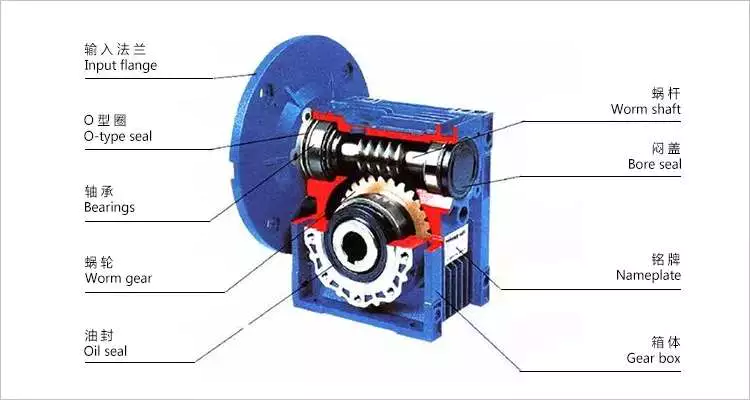
Mechanics
A worm reducer is an auxiliary mechanical device that uses worms to reduce the size of a rotating shaft. These worms have a range of tooth forms. One form is a line weave twist surface. Another is a trapezoid based on a central cross section. The trapezoid can be perpendicular to the tooth cross section, or it can be normal to the root cross section. Other forms include involute helicoids and convolute worms, which use a straight line intersecting the involute generating line.
Worm gears are lubricated with a special lubricant. Because worm gears are complex, it’s important to use the correct lubricant. Worm gear manufacturers provide approved lubricants for their gears. Using unapproved gear oil can damage your reducer’s efficiency. The right lubricant depends on several factors, including load, speed, duty cycle, and expected operating temperatures.
The efficiency of a worm gear reducer depends on several factors, including losses at gear mesh, losses in the bearings, and windage in the oil seal lip. In addition, the worm gear reducer’s efficiency varies with ambient temperature and operating temperature. The worm gear reducer’s efficiency can also vary with the ratio of the load. Moreover, worm gear reducers are subject to break-in.
Worm gear reducers are used in many different applications. They are typically used in small electric motors, but they’re also used in conveyor systems, presses, elevators, and mining applications. Worm gears are also commonly found in stringed musical instruments.
Worm gears have excellent reduction ratios and high Agknx multiplication, and they’re often used as speed reducers in low to medium-speed applications. However, the efficiency of worm gear reducers decreases with increasing ratios.
Sizes
Worm reducers come in different sizes and tooth shapes. While the tooth shape of one worm is similar to the other, different worms are designed to carry a different amount of load. For example, a circular arc worm may have a different tooth shape than one with a secondary curve. Worm gears can also be adjusted for backlash. The backlash is the difference between the advancing and receding arc.
There are two sizes of worm reducers available from Agknx Transmission. The SW-1 and SW-5 models offer ratios of 3.5:1 to 60:1 and 5:1 to 100:1 respectively. The size of the worm reducer is determined by the required gear ratio.
Worm gears have different thread counts. One is based on the central cross-section of the worm, and the other is on the right. Worm gears can have either a single or double thread. Single-threaded gears will reduce speed by 50 percent, while double-threaded gears will reduce speed by 25 percent.
Worm gear reducers are lightweight and highly reliable. They can accommodate a variety of NEMA input flanges and hollow output bore sizes. Worm reducers can be found at 6 regional warehouses, with prepaid freight. To make a purchasing decision, you should consider the horsepower and Agknx requirements of your specific application.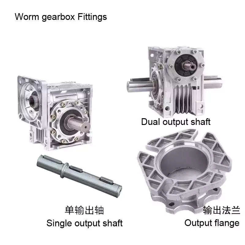
Applications
The Worm Reducer market is a global business that is dominated by the North American and European regions. The report provides in-depth information on the market trends, key challenges, and opportunities. It also examines the current state of the industry and projects future market growth. The report is organized into segments based on product type, major geographical regions, and application. It also presents statistics and key data about the market.
Worm gear reducers have many applications. They can be used to increase the speed of convey belts. They also help reduce noise. Worm gears have many teeth that touch the gear mesh, which makes them quieter. Moreover, the worm gears require only a single stage reducer, reducing the number of moving parts in the system.
The worm gear has long life and is suitable for different industries. It is a perfect choice for elevators and other applications that need fast stopping and braking. Its compact size and ability to hold a load make it suitable for these applications. It also prevents the load from free-falling as a result of a sudden braking. Worm gears can also be used in heavy-duty machinery such as rock crushers.
Worm gears are similar to ordinary gears except that they transfer motion at a 90-degree angle. As a result, the worm gears are extremely quiet, making them a suitable option for noise sensitive applications. They are also excellent for low-voltage applications, where the noise is critical.
Worm gears are ideal for applications with space restrictions, because they require fewer gear sets. The worm gears also allow for a smaller gearbox size. Consequently, they are the perfect choice for machines that are space-constrained, such as conveyors and packaging equipment.
Cost
The lifespan of a worm gear reducer is comparable to other gear reducers. Worm gears have a long history of innovation and use in various industries, from shipbuilding to automobile manufacturing. Today, these gear reducers are still popular with engineers. However, there are some things to keep in mind before buying one.
In the first place, a worm reducer needs to be affordable. Generally, a worm reducer costs about $120. The price varies with the brand name and features. Some products are more expensive than others, so be sure to shop around for the best price. In addition, it is important to consider the quality and design of the worm reducer before making a purchase.
Worm gear manufacturers have made significant advancements in materials, design and manufacturing. These advancements, along with the use of advanced lubricants, have resulted in significant increases in efficiency. For example, double enveloping worm gear reducers have improved efficiency by three to eight percentage points. This improvement was achieved through rigorous testing of manufacturing processes and materials. With these improvements, worm gear reducers have become more desirable in today’s market.
Worm reducers are extremely versatile and reliable, and are available in a variety of sizes. Domestic manufacturers usually stock a large selection of reducers, and are often able to ship them the same day you place your order. Most major domestic worm gear reducer manufacturers also share some critical mounting dimensions, such as the output shaft diameter, the mounting hole location, and the overall reducer housing height. Most manufacturers also offer standardized gear ratios. Some manufacturers have also improved gear design and added synthetic lubricants for better performance.
In addition, different tooth shapes of worms can increase their load carrying capacity. They can be used on secondary curves and circular arc cross sections. Moreover, the pitch point defines the boundary of the cross section. The mesh on the receding arc is smoother than that of the advancing arc. However, in the case of negative shifting, most of the mesh is on the receding arc.
Self-locking function
A worm reducer has a self-locking function. When a worm is fitted with all of its addendum teeth, the total number of teeth in the system should be greater than 40. This self-locking function is achieved through the worm’s rack and pinion mechanism. The worm’s self-locking feature can prevent the load from being dropped and is useful for many applications.
The self-locking function of a worm reducer is possible for two main reasons. First of all, a worm reducer uses two or more gears. One gear is placed at the input, and the other gear runs the output shaft. This mechanism produces a torque, which is transmitted to a spur gear.
Worm reducers can be used in a variety of industrial applications. Because of their self-locking function, they are useful for preventing back-driving. They are also helpful for lifting and holding loads. Their self-locking mechanism allows for a large gear reduction ratio without increasing the size of a gear box.
Self-locking gears can be used to prevent back-driving and inertial driving. This is useful for many industries and can prevent backdriving. However, one major disadvantage of self-locking gears is their sensitivity to operating conditions. Lubrication, vibration, and misalignment can affect their reliability.
Embodiments of the invention provide a self-locking mechanism that prevents back-driving but allows forward-driving. The self-locking mechanism may comprise first and second ratchet cams disposed about a gear member. A releasable coupling member may be interposed between the gear member and the ratchet cam. This facilitates selective coupling and decoupling.
The worm reducer has several advantages. Its compact design is ideal for many mechanical transmission systems. It also provides greater load capacity than a cross-axis helical gear mechanism.


editor by czh 2022-12-07