Description
WPDKA Cast Iron Worm Reducer — Product Overview
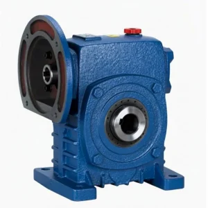
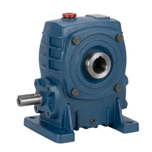
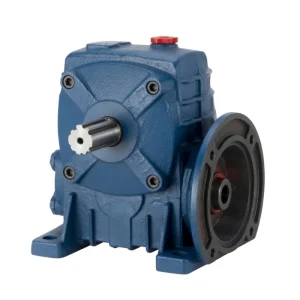
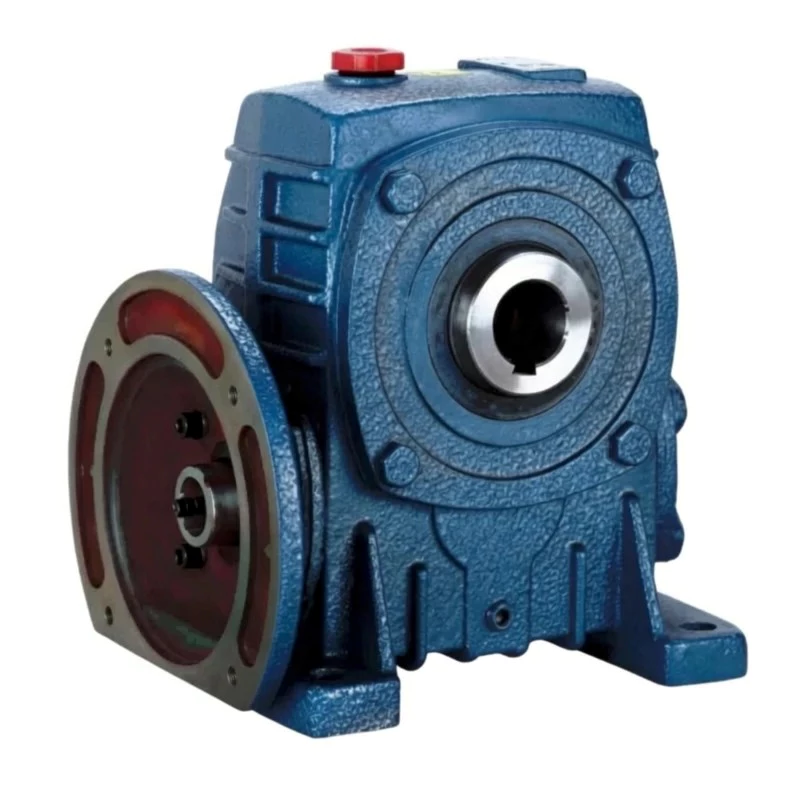
Most drive trains require three separate components between motor and driven shaft: a motor adaptor, a gearbox, and an output coupling. The WPDKA consolidates all three functions into a single cast iron worm reducer. The integrated IEC motor flange mounts the motor directly — no adaptor. The K-type hollow bore output receives the driven shaft directly — no coupling. The D-type split housing enables in-situ worm wheel maintenance — no teardown.
The result is the lowest component count, shortest installed drive length, and fastest maintenance access available in the WP worm reducer series. One WPDKA unit replaces gearbox plus adaptor plus coupling across the full size range of 40–250 mm centre distance.
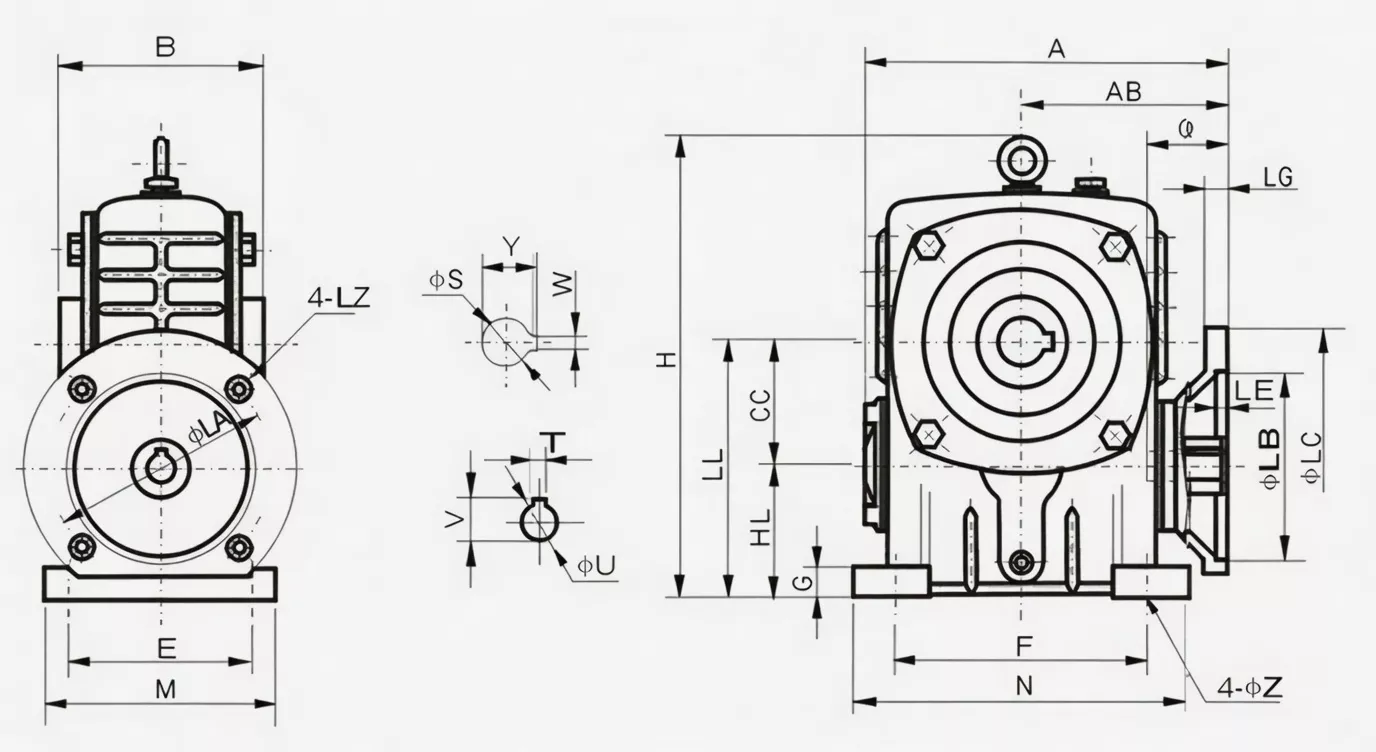
WPDKA Worm Reducer Specifications
| Parameter | Specification |
|---|---|
| Series | Single Speed |
| Housing Structure | D-type split cast iron |
| Input Configuration | IEC motor flange — hollow bore (D-type) |
| Output Configuration | Hollow bore — K-type through-hole |
| Reduction Ratio | 1/5–1/60 |
| Centre Distance | 40–250 mm |
| Mounting | Foot-mount: D-type IEC input + K hollow output |
| Housing Material | FC20+ grey cast iron (GG20) |
| Worm Wheel Material | Tin-bronze ZCuSn10Pb1 |
| Worm Shaft Material | 20CrMnTi, 55–60 HRC surface |
| Lubrication | N220–N320 (−30°C–40°C); N320–N460 (40°C–65°C) |
| Max Oil Temperature | 95°C continuous |
| Weight Range | 5–350 kg |
| Special Feature | Triple function: D-split + IEC input flange + K hollow output — lowest component count |
Size & Performance Data
| Size | Ratio | Input Power (kW) | Output Torque (Nm) | A (mm) | AB (mm) | B (mm) | BB (mm) | Weight (kg) |
|---|---|---|---|---|---|---|---|---|
| 40 | 1/5 | 0.12 | 5–25 | 135 | 75 | 85 | 40 | 5 |
| 50 | 1/5 | 0.18 | 8–40 | 151 | 83 | 105 | 50 | 8 |
| 60 | 1/5 | 0.37 | 11–73 | 167 | 91 | 110 | 60 | 10.5 |
| 70 | 1/5–1/10 | 0.37–0.75 | 23–70 | 200/202 | 109/111 | 130 | 70 | 17 |
| 80 | 1/5–1/10 | 0.75–1.5 | 43–154 | 225 | 125 | 150 | 80 | 25 |
| 100 | 1/5–1/15 | 1.5 | 58–344 | 280 | 148 | 160 | 100 | 38 |
| 120 | 1/5–1/25 | 2.2–3.0 | 72–521 | 333 | 181 | 175 | 120 | 60 |
| 135 | 1/5–1/30 | 3.0–4.0 | 122–690 | 375 | 202 | 210 | 135 | 85 |
| 155 | 1/5–1/60 | 4.0–5.5 | 145–1260 | 448 | 247 | 256 | 155 | 120 |
| 175 | 1/5–1/60 | 5.5–7.5 | 210–1450 | 481 | 262 | 282 | 175 | 150 |
| 200 | 1/5–1/60 | 7.5–11.0 | 623–2856 | 543 | 285 | 320 | 200 | 218 |
| 250 | 1/5–1/60 | 11.0–15.0 | 850–3025 | 615 | 330 | 400 | 250 | 350 |
WPDKA Worm Reducer — Core Features
■ D-Type Split Housing — In-Situ Maintenance
Remove the top cover with motor and driven shaft in place. Inspect and replace the worm wheel without disconnecting any drive train element — the fastest maintenance access in the WP series.
■ IEC Motor Flange — Zero Adaptor Plate
Factory-machined IEC 72-1 flange accepts A02/Y-series motors frames 56–355 directly. Eliminates one component and one potential misalignment source from the drive train.
■ K-Type Hollow Bore — No Output Coupling
Precision H7-tolerance bore with GB/T 1095 keyway. Insert the driven shaft directly and key. No coupling lubrication, no coupling fatigue failure, and no coupling mass on the shaft overhang.
■ One Unit Replaces Three Components
WPDKA replaces the motor adaptor plate + gearbox + output coupling, reducing BOM count by two components, installation time by approximately 50%, and total installed drive length by 60–200 mm depending on size.
■ FC20+ Cast Iron Housing — Full Rigidity
Triple-feature architecture does not compromise structural integrity. The WPDKA retains FC20+ cast iron with 95°C continuous oil temperature rating, identical to the standard WPA.
■ Sizes 40–250 mm — Full Power Range Covered
Covers 0.12 kW (size 40) to 15.0 kW (size 250), with output torques from 5 Nm to 3,025 Nm — the complete range of standard OEM machine building and industrial conveyor drives.
WPDKA Worm Reducer — Industry Applications

⚒ OEM Compact Machine Design
Machine builders achieving the tightest possible drive envelope choose the WPDKA — IEC motor mounts direct, driven shaft inserts direct, and split cover provides maintenance access without disassembly.
⚙ Chemical & Wastewater Agitators
Agitator shafts insert through the hollow bore with no exposed coupling in corrosive process fluids. D-type housing enables annual worm wheel checks during routine maintenance windows without removing the motor.
⚊ Compact Conveyor Drive Packages
Shaft-mounted WPDKA with IEC motor reduces the installed height of conveyor head drive assemblies by eliminating adaptor and coupling components — critical in low-headroom installations.
⚙ Construction Equipment Drives
Robust FC20+ cast iron handles the shock loading of construction equipment drives. Triple-function design simplifies the drive system bill of materials for equipment manufacturers.
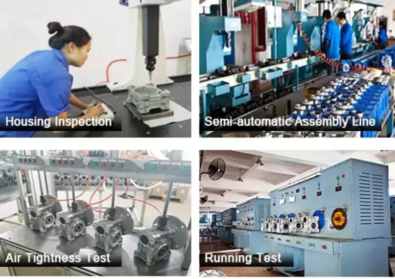
Ever Power Manufacturing Quality — WPDKA Worm Reducer
■ ISO 9001:2000 Certified
Every unit is manufactured under ISO 9001:2000 quality management. Raw material inspection, in-process checks, and final testing are all documented and traceable to each unit’s serial number.
■ CE Marking — EU Machinery Directive 2006/42/EC
Full CE compliance confirms adherence to European safety and design standards for mechanical power transmission, supporting export to EU, UK, Australian, and New Zealand markets.
■ Pre-Shipment Testing: Noise, Leak, Torque
Every unit passes three tests before shipping: noise below 68 dB(A) at rated load, 30-minute pressurisation leak test, and torque transmission within ±5% of rated value. Non-conforming units are reworked — not shipped.
■ FC20+ Material Certification
Housing castings are verified by mill certificates for FC20 grade: minimum 220 MPa tensile strength, 160–200 HB hardness. Ultrasonic defect testing is performed on size 135 and above.
WPDKA Worm Reducer — Customer Reviews
“WPDKA eliminated three separate components from our mixer drive BOM — motor adaptor, gearbox, and output coupling. Assembly time per unit dropped from 45 minutes to 12 minutes.”
“Used WPDKA-120 on our packaging line drives. Direct motor flange and hollow bore output gave us the most compact drive envelope we’ve achieved. No alignment issues after 12 months continuous running.”
“WPDKA on our sewage treatment agitators. Split housing made our first annual inspection very fast — full access with motor in-place. Worm wheel in excellent condition after 9,000 hours.”
“Very good multi-function unit. The DKA combination is exactly what our compact OEM conveyor design needed. Would welcome a larger selection in the 155–200 mm range.”
Frequently Asked Questions — WPDKA Worm Reducer
Get Your WPDKA Quote Today
Tell Ever Power your application requirements — torque, ratio, mounting, and shaft dimensions. Engineering response within 24 hours. OEM custom specifications, bulk pricing, and global shipping available.