Product Description
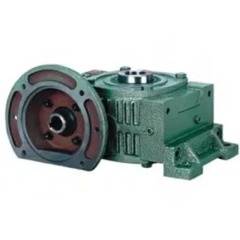
Helical Worm Gear Low Noise Cast Iron HT250 Ground Parallel Shaft Best Speed Reducer Gearbox Die Casting Lumen Good Price Nmrv High Efficiency Helical Worm Gear
F series gear reducer is 1 kind of parallel shaft helical gear reducer , which consist of 2 or 3 stages helical gears (relate to gear ratio) in the same case . The hard tooth surface gear use the high quality alloy steel ,the process of carburizing and quenching, grinding ,which give it follow characters :Stable transmission ,low noise and temperature ,high loading ,long working lift . Wide application ,specialize in Metallurgy ,Sewage treatment,
Chemical Industry , Pharmacy ,Agriculture equipment and Oil industry.
Specifications:
1) Output speed: 0.6~1,571r/min
2) Output torque: up to 21700N.m
3) Motor power: 0.12~200kW
4) Mounted form: foot-mounted and flange-mounted mounting
| Product Name | SLK Series Rigid Tooth helical bevel reducer |
| Gear Material | 20CrMnTi |
| Case Material | HT250 |
| Shaft Material | 20CrMnTi |
| Gear Processing | Grinding finish by HOFLER Grinding Machines |
| Color | Customized |
| Noise Test | 65~70dB |
| Efficiency | 94%~98% (depends on the transmission stage) |
| Lubricating oil | Shell Omala synthetic oil or mineral oil , or similar brand |
| Heat treatment | tempering, cementiting, quenching,etc. |
| Brand of bearings | C&U bearing, ZWZ,LYC, HRB, SKF,NSK and so on |
| Brand of oil seal | NAK or other brand |
| Temp. rise (MAX) | 40 ° |
| Temp. rise (Oil)(MAX) | 50 ° |
| Vibration | ≤20µm |
company information
/* January 22, 2571 19:08:37 */!function(){function s(e,r){var a,o={};try{e&&e.split(“,”).forEach(function(e,t){e&&(a=e.match(/(.*?):(.*)$/))&&1
| Application: | Motor, Electric Cars, Motorcycle, Machinery, Marine, Toy, Agricultural Machinery, Car |
|---|---|
| Hardness: | Hardened Tooth Surface |
| Installation: | Horizontal Type |
| Layout: | Coaxial |
| Type: | Worm Reducer |
| Output Torque: | 3.5~21700n.M |
| Samples: |
US$ 999/Piece
1 Piece(Min.Order) | |
|---|
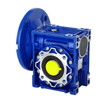
How to Install and Align a Worm Reducer Properly
Proper installation and alignment of a worm reducer are crucial for ensuring optimal performance and longevity. Follow these steps to install and align a worm reducer:
- Preparation: Gather all the necessary tools, equipment, and safety gear before starting the installation process.
- Positioning: Place the worm reducer in the desired location, ensuring that it is securely mounted to a stable surface. Use appropriate fasteners and mounting brackets as needed.
- Shaft Alignment: Check the alignment of the input and output shafts. Use precision measurement tools to ensure that the shafts are parallel and in line with each other.
- Base Plate Alignment: Align the base plate of the reducer with the foundation or mounting surface. Ensure that the base plate is level and properly aligned before securing it in place.
- Bolt Tightening: Gradually and evenly tighten the mounting bolts to the manufacturer’s specifications. This helps ensure proper contact between the reducer and the mounting surface.
- Check for Clearance: Verify that there is enough clearance for any rotating components or parts that may move during operation. Avoid any interference that could cause damage or performance issues.
- Lubrication: Apply the recommended lubricant to the worm reducer according to the manufacturer’s guidelines. Proper lubrication is essential for smooth operation and reducing friction.
- Alignment Testing: After installation, run the worm reducer briefly without a load to check for any unusual noises, vibrations, or misalignment issues.
- Load Testing: Gradually introduce the intended load to the worm reducer and monitor its performance. Ensure that the reducer operates smoothly and efficiently under the load conditions.
It’s important to refer to the manufacturer’s installation guidelines and specifications for your specific worm reducer model. Proper installation and alignment will contribute to the gearbox’s reliability, efficiency, and overall functionality.
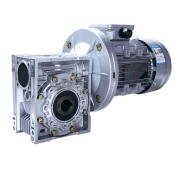
Does a Worm Reducer Require Frequent Maintenance?
Worm reducers generally require less frequent maintenance compared to some other types of gearboxes due to their design and operating characteristics. However, maintenance is still essential to ensure optimal performance and longevity. Here are some key points to consider:
- Lubrication: Proper lubrication is crucial for worm gearboxes. Regularly check the lubricant level and quality to prevent wear and overheating. Lubricant should be changed as recommended by the manufacturer.
- Inspections: Periodically inspect the gearbox for signs of wear, damage, or oil leaks. Check for any unusual noises, vibrations, or changes in performance that could indicate a problem.
- Tightening and Alignment: Check and tighten any loose fasteners and ensure that the gearbox is properly aligned. Misalignment can lead to increased wear and reduced efficiency.
- Seal Maintenance: Inspect and maintain seals to prevent oil leakage and contaminants from entering the gearbox.
- Cleaning: Keep the gearbox clean from debris and contaminants that could affect its performance. Regular cleaning can prevent premature wear and damage.
- Load and Speed: Ensure that the gearbox is operating within its rated load and speed limits. Exceeding these limits can lead to accelerated wear and potential failure.
- Environmental Conditions: Consider the operating environment of the gearbox. Extreme temperatures, humidity, and other factors can impact the gearbox’s performance and longevity.
While worm gearboxes are known for their durability and self-locking feature, neglecting maintenance can lead to premature wear, reduced efficiency, and potential breakdowns. Following the manufacturer’s recommendations for maintenance intervals and procedures is essential to keep the worm reducer in optimal condition.

Preventing Backlash in a Worm Gearbox
Backlash in a worm gearbox can lead to reduced accuracy, positioning errors, and decreased overall efficiency. Here are steps to prevent or minimize backlash:
- High-Quality Components: Use high-quality worm gears and worm wheels with tight manufacturing tolerances. Precision components will help reduce backlash.
- Proper Meshing: Ensure the worm gear and worm wheel are properly aligned and meshed. Improper meshing can lead to increased backlash.
- Preload: Applying a small amount of preload to the worm gear can help reduce backlash. However, excessive preload can increase friction and wear.
- Anti-Backlash Mechanisms: Consider using anti-backlash mechanisms, such as spring-loaded systems or adjustable shims, to compensate for any inherent backlash.
- Lubrication: Proper lubrication can reduce friction and play a role in minimizing backlash. Use a lubricant that provides good film strength and reduces wear.
- Maintenance: Regularly inspect and maintain the gearbox to identify and address any changes in backlash over time.
It’s important to strike a balance between reducing backlash and maintaining smooth operation. Consulting with gearbox experts and following manufacturer guidelines will help you optimize your worm gearbox’s performance while minimizing backlash.


editor by CX 2024-04-08
China Standard S Series CZPT Shaft Helical Worm Gearbox Tractor Pto Multiplier Gearbox 11kw Gearbox Marine Transmission Gear Box synchromesh gearbox
Product Description
Product Parameters
S series geared motor speed reducer with 90 Degree Gear box
Components:
1. Housing: Cast Iron
2. Gears: Helical-worm Gears
3. Input Configurations: Equipped with Electric Motors
Solid Shaft Input, IEC-normalized Motor Flange
4. Applicable Motors:
Single Phase AC Motor, Three Phase AC Motor
Brake Motors, Inverter Motors
Multi-speed Motors, Explosion-proof Motor
Roller Motor
5. Output Configurations: CHINAMFG Shaft Output
Hollow Shaft Output.
Features:
1. Modular design, compact structure
2. Low noise
3. Hollow output shaft with keyed connection, shrink disk, or torque arm
4. Can be combined with other types of gearboxes (Such as R Series, UDL Series)
|
Models |
Output Shaft Dia. |
Input Shaft Dia. |
Power(kW) |
Ratio |
Max. Torque(Nm) |
|
|
Solid Shaft |
Hollow Shaft |
|||||
|
S38 |
20mm |
20mm |
16mm |
0.18~0.75 |
10.27~152 |
90 |
|
S48 |
25mm |
25/30mm |
16mm |
0.18~1.5 |
11.46~244.74 |
170 |
|
S58 |
30mm |
30/35mm |
16mm |
0.18~3 |
10.78~196.21 |
295 |
|
S68 |
35mm |
40/45mm |
19mm |
0.25~5.5 |
11.55~22 |
520 |
|
S78 |
45mm |
50/60mm |
24mm |
0.55~7.5 |
9.96~241.09 |
1270 |
|
S88 |
60mm |
60/70mm |
28mm |
0.75~15 |
11.83~222 |
2280 |
|
S98 |
70mm |
70/90mm |
38mm |
1.5~22 |
12.75~230.48 |
4000 |
/* January 22, 2571 19:08:37 */!function(){function s(e,r){var a,o={};try{e&&e.split(“,”).forEach(function(e,t){e&&(a=e.match(/(.*?):(.*)$/))&&1
| Hardness: | Hardened Tooth Surface |
|---|---|
| Installation: | 90 Degree |
| Layout: | Expansion |
| Gear Shape: | Bevel Gear |
| Step: | Single-Step |
| Type: | Gear Reducer |
| Samples: |
US$ 150/Piece
1 Piece(Min.Order) | |
|---|
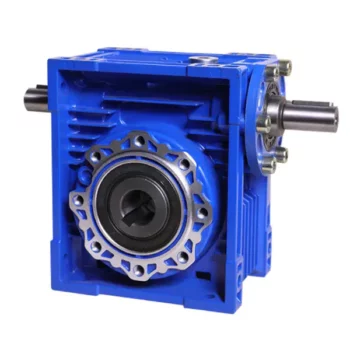
What are the Noise Levels Associated with Worm Gearboxes?
The noise levels associated with worm gearboxes can vary depending on several factors, including the design, quality, operating conditions, and maintenance of the gearbox. Here are some key points to consider:
- Design and Quality: Well-designed and high-quality worm gearboxes tend to produce lower noise levels. Factors such as gear tooth profile, precision manufacturing, and proper alignment can contribute to reduced noise.
- Gear Engagement: The way the worm and worm wheel engage and mesh with each other can impact noise levels. Proper tooth contact and alignment can help minimize noise during operation.
- Lubrication: Inadequate or improper lubrication can lead to increased friction and wear, resulting in higher noise levels. Using the recommended lubricant and maintaining proper lubrication levels are important for noise reduction.
- Operating Conditions: Operating the gearbox within its specified load and speed limits can help prevent excessive noise generation. Overloading or operating at high speeds beyond the gearbox’s capabilities can lead to increased noise.
- Backlash: Excessive backlash or play between the gear teeth can lead to impact noise as the teeth engage. Proper backlash adjustment can help mitigate this issue.
- Maintenance: Regular maintenance, including gear inspection, lubrication checks, and addressing any wear or damage, can help keep noise levels in check.
It’s important to note that while worm gearboxes can produce some noise due to the nature of gear meshing, proper design, maintenance, and operation can significantly reduce noise levels. If noise is a concern for your application, consulting with gearbox manufacturers and experts can provide insights into selecting the right gearbox type and implementing measures to minimize noise.
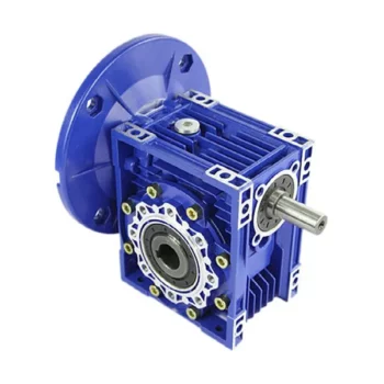
Energy Efficiency of a Worm Gearbox: What to Expect
The energy efficiency of a worm gearbox is an important factor to consider when evaluating its performance. Here’s what you can expect in terms of energy efficiency:
- Typical Efficiency Range: Worm gearboxes are known for their compact size and high gear reduction capabilities, but they can exhibit lower energy efficiency compared to other types of gearboxes. The efficiency of a worm gearbox typically falls in the range of 50% to 90%, depending on various factors such as design, manufacturing quality, lubrication, and load conditions.
- Inherent Losses: Worm gearboxes inherently involve sliding contact between the worm and worm wheel. This sliding contact generates friction, leading to energy losses in the form of heat. The sliding action also contributes to lower efficiency when compared to gearboxes with rolling contact.
- Helical-Worm Design: Some manufacturers offer helical-worm gearbox designs that combine elements of helical and worm gearing. These designs aim to improve efficiency by incorporating helical gears in the reduction stage, which can lead to higher efficiency compared to traditional worm gearboxes.
- Lubrication: Proper lubrication plays a significant role in minimizing friction and improving energy efficiency. Using high-quality lubricants and ensuring the gearbox is adequately lubricated can help reduce losses due to friction.
- Application Considerations: While worm gearboxes might have lower energy efficiency compared to other types of gearboxes, they still offer advantages in terms of compactness, high torque transmission, and simplicity. Therefore, the decision to use a worm gearbox should consider the specific requirements of the application, including the trade-off between energy efficiency and other performance factors.
When selecting a worm gearbox, it’s essential to consider the trade-offs between energy efficiency, torque transmission, gearbox size, and the specific needs of the application. Regular maintenance, proper lubrication, and selecting a well-designed gearbox can contribute to achieving the best possible energy efficiency within the limitations of worm gearbox technology.
Can a Worm Gearbox Provide High Torque Output?
Yes, a worm gearbox is capable of providing high torque output due to its unique design and principle of operation. Worm gears are known for their high torque multiplication capabilities, making them suitable for applications that require significant torque transfer.
The torque output of a worm gearbox is influenced by several factors:
- Lead Angle: The lead angle of the worm affects the mechanical advantage of the gear system. A larger lead angle can result in higher torque output.
- Worm Diameter: A larger diameter worm can offer increased torque output as it provides more contact area with the gear.
- Gear Ratio: The gear ratio between the worm and the gear determines the torque multiplication factor. A higher gear ratio leads to higher torque output.
- Lubrication: Proper lubrication is essential to minimize friction and ensure efficient torque transmission.
- Material and Quality: High-quality materials and precision manufacturing contribute to the gearbox’s ability to handle high torque loads.
Due to their ability to provide high torque output in a compact form factor, worm gearboxes are commonly used in various industrial applications, including heavy machinery, construction equipment, conveyor systems, and more.


editor by CX 2024-03-13
China OEM R F K S Series Parallel Shaft Inline Gear Box Speed Reducer Reducer Worm Bevel Helical Geared Motor Gearbox gearbox design
Product Description
Technical data:
1,output torque:200-50000(N.m)
2,rated power:0.18-200(kw)
3,input speed:≤1500 (rpm)
4,output speed:≤280(rpm)
5,transmission ratio:≥5.36
6,series:3
7,install form:M1-M6
8,Model no. :K/KA/KF/KAF/KH/KHF(37/47/57/67/77/87/97/107/127/157/167/187)
Other
1,Driving in a variety of forms: motor straight league, user with motor, pulley, wheel drive, couplings straight league drive, the handwheel device etc
2,Output in a variety of forms: can hollow shaft output and CZPT shaft output, hollow shaft flange and CZPT shaft flange, hollow shaft torque arm type, CZPT shaft torque arm type, etc
3,Installed in a variety of forms: can base mounting, flange installation, torque arm installation, etc
| Type | 37 | 47 | 57 | 67 | 77 | 87 | 97 | 107 | 127 | 157 | 167 | 187 |
| Structure form | K KA KF KAF KAZ KAT KAB | |||||||||||
| Input power(KW) | 0.18-3 | 0.18-3 | 0.18-5.5 | 0.18-5.5 | 0.37-11 | 0.75-22 | 1.1-30 | 3-45 | 7.5-90 | 11-160 | 11-200 | 18.5-200 |
| Transmission ratio | 5.36-106.38 | 5.81-131.87 | 6.57-145.14 | 7.14-144.79 | 7.24-192.18 | 7.19-197.37 | 8.95-176.05 | 8.74-1410.46 | 8.68-146.07 | 12.65-150.41 | 17.28-163.91 | 170.27-180.78 |
| Allowable torque(N.m) | 200 | 400 | 600 | 820 | 1550 | 2700 | 4300 | 8000 | 13000 | 18000 | 32000 | 50000 |
| Weight(kg) | 11 | 20 | 27 | 33 | 57 | 85 | 130 | 250 | 380 | 610 | 1015 | 1700 |
Product Description
-K Series Helical Bevel Gearbox
K series gear reducer, manufactured according to international technical requirements, has a high scientific and technological content; Space saving, reliable and durable, high overload capacity, power up to 132KW; Low energy consumption, superior performance, reducer efficiency up to 95%
It is designed and manufactured on the basis of module combination system. There are a lot of motor combinations, installation forms and structural schemes. The transmission ratio is classified carefully to meet different operating conditions and realize electromechanical integration.
High transmission efficiency, low energy consumption and superior performance.
Reinforced high rigid cast iron box; The hardened gear is made of high-quality alloy steel. Its surface is carburized, quenched and hardened, and the gear is finely ground. It features stable transmission, low noise, large bearing capacity, low temperature rise, and long service life. Performance and characteristics:
1. The gear is carburized and quenched with high-quality alloy, the hardness of the tooth surface is up to 60 ± 2hrc, and the grinding accuracy of the tooth surface is up to 5-6
2. The computer modification technology is used to pre modify the gear, which greatly improves the bearing capacity of the reducer
3. Complete modular structure design is adopted from the box to the internal gear, which is suitable for large-scale production and flexible selection
4. The standard reducer models are divided according to the form of decreasing torque. Compared with the traditional equal proportion division, they are more in line with customer requirements and avoid power waste
5. It is designed and manufactured by cad/cam to ensure the stability of quality
6. Multiple sealing structures are adopted to prevent oil leakage
7. Multi directional noise reduction measures to ensure the excellent low noise performance of the reducer
8. The installation mode of Liyi products is flexible, which makes it easy for customers to choose K57 reducer, K67 reducer, K77 reducer, K87 reducer, K97 reducer, KA87 reducer, KA97 reducer, KA107 reducer, KA127 reducer
Product Features
1. Input mode: Coupled motor, belted motor, input shaft or connection flange.
2. Output: Right angle
3. Compact structure. Rigid tooth face. Carrying greater torque, high loading capacity.
4.High precision gear, ensuring the unit to operate stably, smooth transmission.
5. Low noise, long lifespan. Large overlap coefficient, abrasion resistant.
Our process of production
Our product line
| Hardness: | Hardened Tooth Surface |
|---|---|
| Installation: | 90 Degree |
| Layout: | Expansion |
| Gear Shape: | Bevel Gear |
| Step: | Single-Step |
| Type: | Gear Reducer |
| Samples: |
US$ 1000/Piece
1 Piece(Min.Order) | |
|---|
Can a Worm Gearbox Provide High Torque Output?
Yes, a worm gearbox is capable of providing high torque output due to its unique design and principle of operation. Worm gears are known for their high torque multiplication capabilities, making them suitable for applications that require significant torque transfer.
The torque output of a worm gearbox is influenced by several factors:
- Lead Angle: The lead angle of the worm affects the mechanical advantage of the gear system. A larger lead angle can result in higher torque output.
- Worm Diameter: A larger diameter worm can offer increased torque output as it provides more contact area with the gear.
- Gear Ratio: The gear ratio between the worm and the gear determines the torque multiplication factor. A higher gear ratio leads to higher torque output.
- Lubrication: Proper lu
How to Install and Align a Worm Reducer Properly
Proper installation and alignment of a worm reducer are crucial for ensuring optimal performance and longevity. Follow these steps to install and align a worm reducer:
- Preparation: Gather all the necessary tools, equipment, and safety gear before starting the installation process.
- Positioning: Place the worm reducer in the desired location, ensuring that it is securely mounted to a stable surface. Use appropriate fasteners and mounting brackets as needed.
- Shaft Alignment: Check the alignment of the input and output shafts. Use precision measurement tools to ensure that the shafts are parallel and in line with each other.
- Base Plate Alignment: Align the base plate of the reducer with the foundation or mounting surface. Ensure that the base plate is level and properly aligned before securing it in place.
- Bolt Tightening: Gradually and evenly tighten the mounting bolts to the manufacturer’s specifications. This helps ensure proper contact between the reducer and the mounting surface.
- Check for Clearance: Verify that there is enough clearance for any rotating components or parts that may move during operation. Avoid any interference that could cause damage or performance issues.
- Lubrication: Apply the recommended lubricant to the worm reducer according to the manufacturer’s guidelines. Proper lubrication is essential for smooth operation and reducing friction.
- Alignment Testing: After installation, run the worm reducer briefly without a load to check for any unusual noises, vibrations, or misalignment issues.
- Load Testing: Gradually introduce the intended load to the worm reducer and monitor its performance. Ensure that the reducer operates smoothly and efficiently under the load conditions.
It’s important to refer to the manufacturer’s installation guidelines and specifications for your specific worm reducer model. Proper installation and alignment will contribute to the gearbox’s reliability, efficiency, and overall functionality.
brication is essential to minimize friction and ensure efficient torque transmission.
- Material and Quality: High-quality materials and precision manufacturing contribute to the gearbox’s ability to handle high torque loads.
Due to their ability to provide high torque output in a compact form factor, worm gearboxes are commonly used in various industrial applications, including heavy machinery, construction equipment, conveyor systems, and more.


editor by CX 2023-08-17