Сипаттама
WPEDKA Double Speed Cast Iron Worm Reducer — Product Overview
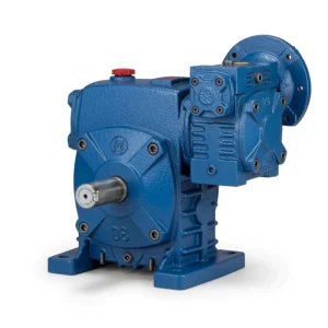
Single-stage worm reducers achieve ratios up to 1/60. When applications demand 1/200, 1/500, or 1/900 — solar trackers, valve actuators, slow-speed conveyors, and positioning drives — a second worm stage is the engineering answer. The WPEDKA places two matched worm stages in tandem in a single cast iron housing, delivering ratios from 1/200 to over 1/900 in one compact, foot-mount unit with no intermediate shafting, no external coupling between stages, and no additional mounting frame.
D-split maintenance access, IEC direct motor mount, K hollow bore output, and two-stage extreme ratio — all within a sin… The dual-stage architecture uses matched tin-bronze worm wheels and 20CrMnTi worm shafts at both stages, providing consistent mesh quality and noise performance across the full ultra-high ratio range.
WPEDKA Double Speed Worm Reducer Specifications
| Параметр | Техникалық сипаттама |
|---|---|
| Сериялар | Double Speed WPED+K |
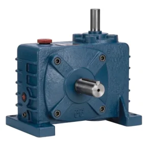
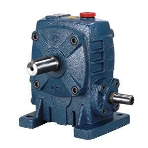
| Тұрғын үй | D-type split cast iron, dual-stage |
| Кіріс | IEC motor flange — D-type |
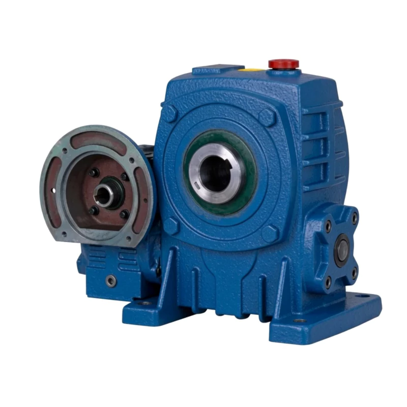
| Шығыс | Hollow bore — K-type |
| Арақатынас диапазоны | 1/200–1/900+ |
| Size Combinations | 40–70 to 155–250 mm |
| Орнату | Foot-mount, D-split, IEC flange, K hollow output |
| Корпус материалы | FC20+ grey cast iron, dual-chamber |
| Worm Wheels | Matched pair tin-bronze ZCuSn10Pb1, both stages |
| Worm Shafts | 20CrMnTi case-hardened 55–60 HRC, both stages |
| Майлау | N220–N320 (−30°C–40°C); N320–N460 (40°C–65°C), both chambers |
| Максималды май температурасы | 95°C үздіксіз |
| Салмақ диапазоны | 19–470 kg |
| Негізгі мүмкіндік | D-split + IEC flange + K hollow bore + double-stage — maximum integration ultra-high ratio |
Size Combination & Performance Data
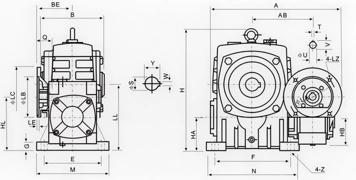
| Size Combo | Қатынас | Кіріс (кВт) | Шығыс моменті (Нм) | А (мм) | AA (мм) | AB (мм) | BB (мм) | Салмағы (кг) |
|---|---|---|---|---|---|---|---|---|
| 40–70 | 1/200 | 0.12 | 63–177 | 314 | 153 | 131 | 75 | 19 |
| 50–80 | 1/300 | 0.18 | 97–252 | 314 | 144 | 142 | 83 | 27 |
| 60–100 | 1/400 | 0.37 | 195–561 | 387 | 175 | 169 | 91 | 45 |
| 70–120 | 1/500 | 0.75 | 384–1,166 | 425/445 | 193 | 175 | 109/111 | 75 |
| 80–135 | 1/600 | 1.5 | 616–1,811 | 499 | 226 | 210 | 125 | 103 |
| 100–155 | 1/800 | 1.5 | 854–2,100 | 570 | 269 | 252 | 148 | 147 |
| 120–175 | 1/900 | 3.0 | 1,798–4,463 | 631 | 287 | 255 | 181 | 204 |
| 135–200 | 1/900+ | 4.0 | 2,188–5,830 | 630/680 | 318 | — | 202 | 298 |
| 155–250 | 1/900+ | 5.5 | 2,841–9,066 | 815 | 380 | 385 | 247 | 470 |
WPEDKA Double Speed Worm Reducer — Core Features
■ Four Functions in One Dual-Stage Housing
D-split maintenance access, IEC direct motor mount, K hollow bore output, and two-stage extreme ratio — all within a single FC20+ cast iron dual-chamber housing. The most fully specified unit in the WPE double speed series.
■ IEC Motor Flange — Direct Motor Mount at 1/200–1/900+
Motor bolts directly onto the first-stage IEC flange. No adaptor plate, no coupling between motor and first stage. Simplifies OEM motorised drive BOM at all ultra-high ratio levels.
■ K Hollow Bore — No Output Coupling at 9,066 Nm Maximum
The K-type output bore receives the driven shaft directly even at maximum output torques up to 9,066 Nm (size 155–250). No coupling hardware required at the output shaft interface.
■ D-Split Housing — Dual-Stage In-Situ Access
Remove the housing cover without disturbing motor or driven shaft connections. Both worm stage chambers are accessible for worm wheel inspection and replacement in-situ — minimising planned maintenance time for installed motorised drive systems.
■ Replaces Four Components — Reducer + IEC Adaptor + Output Coupling + Second Frame
WPEDKA eliminates the IEC motor adaptor, the output shaft coupling, and the inter-stage coupling and frame required by two separate single-stage reducers. Single unit, minimum installation hardware.
■ Matched Dual-Stage Worm Wheel Pairs — Consistent Ratio Accuracy
Both stage worm wheel pairs are precision-matched at manufacture. Inter-stage ratio accuracy is maintained across the full operating life — critical for positioning drives where accumulated ratio error must remain within specification.
WPEDKA Worm Reducer — Industry Applications

☀ Solar & Renewable Energy Motorised Drives
WPEDKA direct IEC motor flange and hollow bore output simplify solar tracker and wind turbine yaw drive design — no adaptor, no coupling at either end, in-situ service access for the expected 20+ year field life.
⚒ Electric Valve Actuator Systems
IEC motor direct coupling and K-bore valve stem mounting eliminates both motor adaptor and output coupling from electric actuator assemblies. D-split cover provides in-situ valve actuator inspection access.
⚙ Industrial Positioning Drive Systems
For CNC rotary table indexing, large-format precision turntable drives, and automated gate positioning systems, WPEDKA extreme ratio plus direct connections at both ends simplifies the drive train architecture.
⚊ Shaft-Mounted High-Ratio Conveyor Drives
Shaft-mount WPEDKA directly on conveyor head shafts for extreme-ratio, ultra-slow-speed conveyor drives — IEC motor overhead, hollow bore on shaft, no coupling hardware anywhere in the drive train.
Ever Power Manufacturing Quality — WPE Double Speed Worm Reducer
■ ISO 9001:2000 Certified — Dual-Stage Assembly
Every WPE double speed unit undergoes ISO 9001:2000 quality management at both worm stage assembly levels. Inter-stage alignment and combined ratio accuracy are verified before final assembly.
■ CE белгісі — ЕО машина жасау директивасы 2006/42/EC
Full CE compliance for mechanical power transmission equipment supports export to EU, UK, Australian, and New Zealand markets without re-certification.
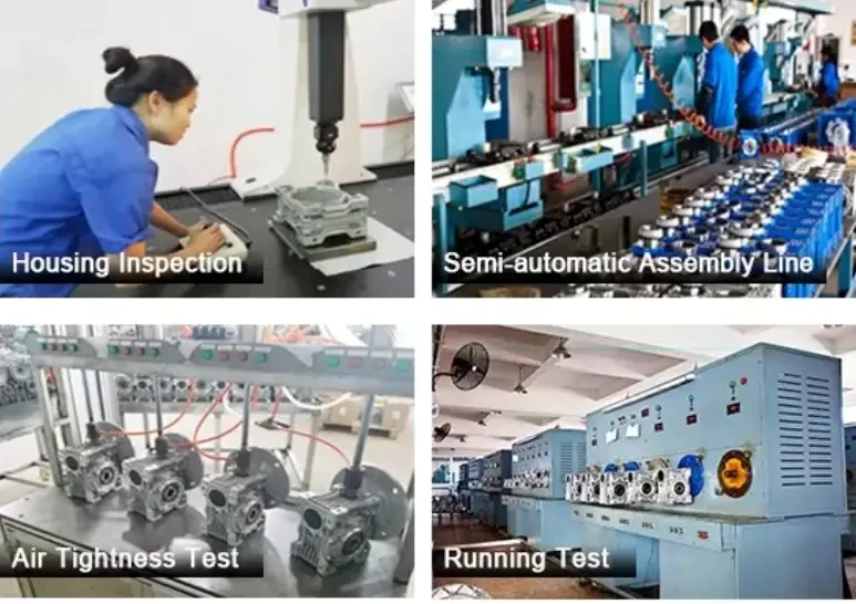
■ Жөнелту алдындағы сынақ: шу, ағып кету, айналу моменті
Noise below 68 dB(A) at rated load, 30-minute pressurisation leak test on both gear chambers, and output torque within ±5% of rated. Non-conforming units reworked before shipment.
■ FC20+ Material Certification — Both Housings
Both the primary and secondary worm housings are verified by FC20 mill certificates: minimum 220 MPa tensile strength, 160–200 HB hardness. Ultrasonic defect testing on size combinations 135–200 and above.
WPEDKA Double Speed Worm Reducer — Customer Reviews
“WPEDKA on our solar tracker motorised drives. IEC motor direct, K-bore on tracker shaft, D-split for 20-year field maintenance plan. No coupling hardware anywhere in the drive — exactly what the system design required.”
“Used WPEDKA on our industrial valve actuator assemblies. Eliminated IEC adaptor, output coupling, and second reducer frame from the BOM. Single unit at 1/800 ratio with 2,100 Nm output. Remarkable simplification.”
“WPEDKA on our precision turntable positioning drives. Direct IEC motor, shaft through K-bore, split cover for annual inspection. Most compact drive architecture we’ve achieved for this application.”
“Excellent integration unit. WPEDKA-80–135 on our conveyor positioning drives. All four features working as described. Would appreciate a formal backlash specification for use in our positioning accuracy calculations.”
Frequently Asked Questions — WPEDKA Double Speed Worm Reducer
Get Your WPEDKA Quote Today
Ever Power компаниясына қолданба талаптарыңызды — айналу моменті, арақатынасы, бекіту және білік өлшемдерін айтыңыз. Инженерлік жауап 24 сағат ішінде. OEM сипаттамалары, көтерме бағалар және жаһандық жеткізу қолжетімді.